
5110000990511000 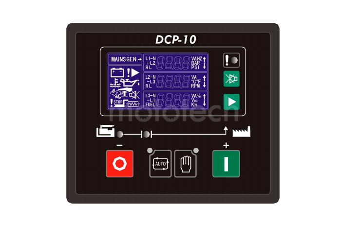
Купить Контроллер FG Wilson DCP-10 производства Великобритания гарантия . Подробные технические характеристики, фотографии, цены
Описание FG Wilson DCP-10
Простой контроллер серии FG Wilson DCP-10 для управления и мониторинга одиночных генераторных установок обеспечивающий ручной и дистанционный запуск.
Настройка параметров контроллера проводится при помощи кнопок на передней панели или при помощи ПК через USB-интерфейс (DCP-10)
Версия DCP-10 в отличии от DCP-20 не имеет следующих функций: измерение мощности ДГУ, обмен через RS232, RS485, USB. Панель стандартно применяется на жидкостных ДГУ FG Wilson мощностью не более 220 кВА.
Возможности контроллера FG Wilson DCP-10:
- Трехфазный вольтметр
- Счетчик моточасов
- LCD экран
- Автозапуск
- Защита от неудачного запуска
- Защита от низкого давления и от высокой температуры двигателя
- Защита пониженных и повышенных оборотов двигателя
- разъем мини-USB
Обзор марки FG Wilson
С 2001 на рынке
Мы успешно реализуем энергетические решения уже 20 лет и накопили опыт решения самых сложных задач
Сервисная служба
Мы обладаем собственной мобильной службой сервиса и ремонта оборудования
Большой склад
Наш склад — это более тысячи наименований оригинальных запчастей и различных расходных элементов
Гарантия качества
Все наши решения защищены и проверены одной из крупнейших СРО. Ответственность застрахована
Manual DCP - 10 Genset Controller DCP-10 I The interpretation of the Symbol: WARNING: A WARNING indicates a potentially hazardous situation which, if not avoided, could result in death, serious personal injury or property damage. CAUTION: A CAUTION indicates a potentially hazardous situation which, if not avoided, could result in damage to equipment or property. NOTE: A NOTE provides other helpful information that does not fall under the warning or caution categories. DCP-10 II WARNING: Read this entire manual pertaining to the work to be performed before installing, operating, or servicing this controller. Practice all plant and safety instructions and precautions. Failure to follow instructions can cause personal injury and/or property damage. The engine or other type of prime mover should be equipped with an overspeed shutdown device to protect against runaway or damage to the prime mover with possible personal injury, loss of life, or property damage. The overspeed shutdown device must be totally independent of the prime mover control system. An over temperature or low pressure shutdown device may also be needed for safety, as appropriate. CAUTION—BATTERY CHARGING To prevent damage to a controller that uses an alternator or battery- charging device, make sure the charging device is turned off before disconnecting the battery from the system. Controllers contain static-sensitive parts. Observe the following precautions to prevent damage to these parts: Do not disassemble the rear back of controller or touch the components and conductors on a printed circuit board. DCP-10 III Contents 1. Description…………………………………………………………………………………………………… 2. Outline Dimension Drawings and Controller Wiring………………………………………………… 3. Panel Operation…………………………………………………………………………………………… 4. Installation Guide………………………………………………………………………………………… 5. Control and Operation Instruction……………………………………………………………………… 6. Measure and Display Data……………………………………………………………………………… 7. Pre-alarm and Shutdown Alarm………………………………………………………………………… 8. Parameter Settings……………………………………………………………………………………… 9. LCD Display and Menu System………………………………………………………………………… 10. Preparation before Starting the Controller…………………………………………………………… 11. Technical Specification………………………………………………………………………………… 1 2 5 6 7 12 13 17 23 28 27 DCP-10 Page 1/27 1. Description The DCP-10 is an Automatic Controller for generator. When running in “AUTO” mode, it starts the Genset after receiving remote start signal and on failure automatically stops the Genset. The generator’s controlling procedure and protection parameters can be modified, which fully meets the Genset’s requirements of automatic start, stop control and basic protection. The module displays fault conditions, operational status and related metering data on panel LCD. LCD has a backlight function so that the operator can read running parameters clearly even in the shadow. The controller has 2 modes: AUTO and MANUAL. Either can be chosen through the panel push button. Measures and displays generator’s output voltage, current, oil pressure, coolant temperature, frequency, DC source voltage, etc. True RMS measure of voltage and current, which ensures the data more accurate. Control the close/open of generator output switch. Equipped with built-in communication interface to configure parameters by PC. All connections of controller are by secure plug and socket, for ease and convenience to connect, move, maintain and replace the device. This manual is only suitable for DCP-10 Automatic control module, user must carefully read this manual first. DCP-10 Page 2/27 2. Outline Dimension Drawings and Controller Wiring 2.1 Following Details: Module Dimensions W120mm×H102mm Panel Cutout W110mm×H92mm Thickness D48mm (without connection) DCP-10 Page 3/27 2.2 Terminal Connections: Pin no. Function Description Signal Dim 1 GEN. V L1-N input 0-300Vac 1mm² 2 GEN. V L2-N input 0-300Vac 1mm² 3 GEN. V L3-N input 0-300Vac 1mm² 4 GEN. Neutral 1mm² 5 Not used 6 Not used 7 I1 Gen current input 0-5A 2.5mm² 8 I2 Gen current input 0-5A 2.5mm² 9 I3 Gen current input 0-5A 2.5mm² 10 Common port for current input 0-5A 2.5mm² 11 LOP sensor or switch signal LOP sensor (<2KΩ) 1mm² 12 HET sensor or switch signal HET sensor (<2KΩ) 1mm² 13 Configurable digital input signal 1 low level is active 1mm² 14 Configurable digital input signal 2 low level is active 1mm² 15 Configurable digital input signal 3 low level is active 1mm² 16 Charge excitation power output if not used, do not connect to negative 1mm² 17 Configurable relay output 1 N.O. contact, 3A/30Vdc 1mm² 18 Configurable relay output 2 N.O. contact, 3A/30Vdc 1mm² 19 Configurable relay output 3 N.O. contact, 3A/30Vdc 1mm² 20 +5V supply Max 100mA, 1mm² 21 Start (Crank) relay output N.O. contact, 3A/30Vdc 1mm² 22 Fuel solenoid relay output N.O. contact, 3A/30Vdc 1mm² 23 Battery supply (+B) 1mm² 24 Battery supply (-B) 12V/24V (8-35Vdc continuous) 1mm² DCP-10 Page 4/27 2.3 Typical Wiring Diagram (12/24V) DC POWER CRANKFUEL CONFIG.OUTPUT LOAD M CONFIG. INPUT REMOTE START COOLANT TEMP. (OR TEMP. SWITCH) OIL PRESSURE (OR OIL SWITCH) DCP-10 Fuse protection with a rating of 0.5A must be provided externally to the Controller. DCP-10 Page 5/27 3. Panel Operation The operation panel consists of 3 sections: LCD display indicating measurement parameters, LED indicator for common failure, and push buttons for Genset and selection of control modes. The LCD circularly displays different measuring parameters. When failure occurs, LCD displays the corresponding fault icon. LCD also has a backlight so that the operator can clearly read information day or night. After pressing any button the backlight will automatically turn off in a certain time. The LCD display and its control push buttons provide a friendly operation interface for the operator to conveniently read information and parameter setting. 3.1 Control buttons and LEDs Function Description Tag Scroll Button Enter into submenu / Modify / confirm modification / scroll menu to display. MUTE / LAMP TEST Button When failure occurs, alarm buzzer sounds. Pressing mute button will mute the sound. LCD displays mute icon. Press and hold mute button for 2sec, all LEDs illuminate simultaneously. AUTO Mode Button / LED The push button is used for selecting “AUTO mode”. When the controller is running in AUTO mode, the LED above the push button illuminated. The activation and deactivation of the “remote start signal input” controls the starting and stopping of the Genset. MAN Mode Button / LED The push button is used for selecting “manual mode”. When the controller is running in MANUAL mode, the LED above the push button illuminated. The Start and Stop push buttons control the starting and stopping of the Genset.. START / VALUE INCREASE “+” Push Button The push button is used for manually start the Genset .When the controller is in MANUAL mode, press this push button to start the generator. When in parameter setting mode, this push button is used to increase values. STOP / RESET / VALUE DECREASE “-” Push Button The push button is used for MANUALLY stops the Genset. When the controller is in MAN mode, press and hold this button more than 2sec to stop the Genset. If failure occurs, press this button, the shutdown alarm lockout can be cleared. When in parameter setting mode, this push button is used to decrease values. COMMEN FAILURE LED LED will flash when pre-alarm (Warning) occurs. LED will illuminate permanently when shutdown alarm occurs. DCP-10 Page 6/27 4. Installation Guide 4.1 The cutout dimensional drawing installed on panel as above attached. The controller is fixed by 2 special fittings. The shock-proof equipment must be mounted if the enclosure is mounted on Genset or other heavy vibrant device. A readily accessible disconnect device shall be incorporated external to the equipment. 4.2 Please refer to the above Typical Wiring Diagram 2.3 for connection. 4.3 Installation of engine LOP and HET sensors: 1211 Terminal 12 Battery negative (Genset enclosure) 11 Description Sensor Com. Port HET sensor/ temp switch LOP sensor/ LOP switch DCP-10 CAUTION: Pin no. “11” and “12” is for “LOP sensor or switch signal” and “HET sensor or switch signal” input respectively. Either switch or sensor can be chosen. When sensor is used, according to the actual situation, increase the cross section area of cable to reduce the cable resistance from controller to engine, which ensures the accuracy of measured values for both oil pressure and engine temperature. If both switches and sensors are required for oil pressure and engine temperature, connect Pin no. “11” and “12” as above, and connect 2 configurable inputs to the switches of oil pressure and temperature, then configure parameters by setting. DCP-10 Page 7/27 5. Control and Operation Instruction 5.1 Operation Mode Setting: The controller has 2 modes: AUTO and MANUAL. Operation Description Press and hold the “AUTO” button for 2sec, the LED above the button is illuminated; the controller is running in “AUTO” mode. Press and hold the “MAN” button for 2sec, the LED above the button is illuminated; the controller is running in “MAN” mode. NOTE: Only 1 mode can be selected from above 2 modes. 5.2 AUTO control Sequence: Controller is running in “AUTO” mode. First of all, one of configurable inputs must be defined as Remote Start Signal. When the remote start signal is active, the controller implements following procedure: The Start delay timer is activated, when it times out the Preheat relay output is energized (if preheat function selected), the timer starts. When it times out, the fuel relay output is energized, and operates the fuel solenoid of the engine. After 300ms delay, the start (crank) relay output is energized; the start motor engages and begins to crank. When the engine speed reaches the crank cutout RPM, the start relay output is de-energized and the safety-on delay starts. When the safety-on times out, if the controller detects that the parameters of the Genset such as voltage, frequency, oil pressure, coolant temperature are normal, and no other failure is detected this indicates the Genset has successfully started and running normally. The LCD displays the Genset Measuremen parameters. When the voltage and frequency of Generator is normal, Gen. Normal LED illuminates, the timer for Gen. On delay is activated, when it times out, GCB close/open relay closes,the transfer switch switches on Gen. The Gen Aux. Switch’s contact feeds back a signal to a configurable input on our controller. GCB closed LED illuminates. NOTE: When remote signal is active, the start-delay timer is activated. During this period, if remote start signal is inactive, the start delay timer terminates immediately; the controller will recovers to the original standby status. During cranking or idle period, if remote start signal is inactive, controller stops the start procedure and recovers to original standby status. DCP-10 Page 8/27 NOTE: While cranking, engine ignites. The start motor will power off when the output frequency of generator reaches the preset value (configurable crank cutout value), or if there are one of the following conditions occur: A. Generator’s voltage reaches 80% of rated voltage; B. Cranking time’s up, C. LOP switch is opened and the delay time’s up. D. Oil pressure switch is opened or oil pressure is higher than crank cutout value. E. Cutout P-delay time’s up. Controller can not implement crank procedure if the frequency of generator reaches the preset value (configurable cranking cutout value) or LOP switch is opened. CAUTION: To avoid damage to the start motor please make sure the generator’s voltage is higher than the measurable value of controller while cranking, since the crank cutout signal is sensed from the generator voltage and frequency. NOTE: Above control procedure, assumes that one of configurable inputs has been configured as Gen Aux. Switch Closed and connects the switch’s N.O. Aux. contact signal to this port. If you do not configure an input as Gen Aux. Switch Closed, then the GCB closed LED illuminates is only an indication that the GCB close/open relay should have been closed. If you have selected idle function, the idle relay will be closed at the same time as the crank relay is closed. The timers of idle and safety-on delay will begin counting down at the same time, and in priority to display the shorter one on the LCD, and the following procedure is the same as above. During the crank period, if the engine can not ignite and controller will not output start signal during crank rest, Fail to Start icon on LCD flashes at this time. Once crank rest timer times out the start relay energizes once again and will attempt to start engine again. The above procedure will be repeated until engine successfully ignites or reaches the preset number of crank attempt. However, if any shutdown alarm occurs during crank, controller will stop cranking immediately and only can be restarted after clearing failure and reset. Fail to Start: when the above procedure repeats again and again and reaches the preset number of crank attempt, the crank relay output is then de-energized. The failure LED illuminates and the LCD displays Fail to Start. CAUTION: If Fail to Start occurs, operator must check the whole Genset system to find out failure reason, only after clearing the failure can press “STOP/RESET” button to relieve fault lock out status, and restart the Genset. Generator shutdown sequence: When the remote start signal is deactivated, the timer for cool down is activated, When it times out, the fuel relay de-energizes, the timer for cool down is activated, DCP-10 Page 9/27 Stop Failure: When cool down times out, the fuel relay opens and the timer for Stop delay begins. When it times out, if controller detects that the voltage and frequency of generator or oil pressure of engine are greater than the preset values, the Fail to stop LED illuminates and the LCD displays Fail to stop. NOTE: After stop failure, the controller will not energize the crank relay output if the failure has not been removed and the controller reset. 5.3 MAN control sequence: Controller is in “MANUAL” mode. Generator starting sequence: Pressing “START” button the fuel relay energises, and operates the fuel solenoid of engine.After 300ms delay, the start relay output is energized, the start motor engages and begins to crank. When the engine speed reaches the crank cutout RPM, the start relay output is de-energized and the safety-on delay starts. When the safety-on times out, if the controller detects that the parameters of the Genset such as voltage, frequency, oil pressure and coolant temperature are normal, and no other failure is detected this indicates the Genset has successfully started and running normally. The LCD displays the Genset Measurement parameters. When generator is running normally, GCB close/open relay will not close automatically. Manually close the Gen switch, Gen is on load, the Gen Aux. Switch’s contact feeds back the signal to a configurable input on our controller, Gen. Normal LED illuminates. 5.4 The start and stop sequence of engine whose fuel solenoid is N. O. type: Start control sequence: During the starting sequence, the fuel relay of controller will not energize, fuel solenoid is no power, so no signal is required for fuel solenoid to activate. Stop control sequence: During the stopping sequence, the fuel relay energizes, fuel solenoid is on power and energizes, and the engine begins to stop. After a delay (same as stop delay) fuel relay de-energizes, disconnecting the supply for the fuel solenoid. Other control sequence is same as engine whose fuel solenoid is N. C. type. NOTE: When the controller is in “MANUAL” mode and Gen. Normal LED illuminates, you must define one configurable input as Gen Aux. Switch Closed and connect the switch’s N.O. Aux. contact signal to this port, otherwise the GCB closed LED will not illuminate. DCP-10 Page 10/27 5.5 Idle function: For idle function configure one of the configurable outputs as idle. Refer to the flow chart 5.7 for start and stop for idle control flows. 5.6 Preheat function: For Preheat function, configure one of the configurable outputs as Preheat. The controller has 3 selectable preheat control modes as below: Mode 1 — during preheat time, preheat relay output energizes. Mode 2 — during preheat time, preheat relay output energizes until the successful ignition. Mode 3 — during preheat time, preheat relay output energizes until safety-on delay times out. During crank period, the Preheat relay output will not energize in any of above modes. Refer to the flow chart 5.7 for start and stop for Preheat control flows. When the Preheat relay output energizes, LCD displays the icon of preheat operating status: DCP-10 Page 11/27 5.7 Flow chart for start and stop T1- start delay T2- crank time T3- pre-heat time T4- safety-on delay T5- idle time T6- stop delay NOTE: If T4 is longer than T5, low oil pressure protection is ignored during T5. If T4 is shorter than T5, low oil pressure protection becomes effective after T4 in T5. DCP-10 Page 12/27 6. Measure and Display Data Gen phase voltage L1-N L2-N L3-N Gen line voltage L1-L2 L2-L3 L3-L1 Generator current I1 I2 I3 Generator frequency Hz Engine speed RPM (signal derived from generator frequency) Engine oil pressure BAR / PSI (signal from engine LOP sensor) Engine coolant temperature ℃/℉ (signal from engine HET sensor) Battery voltage Vdc Genset Running hour Hour DCP-10 Page 13/27 7. Pre-alarm and Shutdown Alarm 7.1 Pre-alarm (Warning) NOTE: (Pre-alarms are non-critical failure conditions and do not affect the operation of the generator system, they serve for drawing the operators’ attention to an undesirable condition so they can remove it to ensure continuous running of the system. When Pre-alarms occur, the LED indicator flashes, but failure will not be locked out and the unit will not shutdown. Once the Pre-alarm failure is removed the Pre-alarm LED will automatically turn off.) Pre-alarm / Description LCD Display CHARGE FAILURE: After safety-on times up, if the charging voltage from the excitation contact of alternator is lower than the “charge V Pre-alarm”, the common failure LED indicator ( ) flashes, the LCD displays Charge failure icon: BATT. UNDER VOLT: if controller detects that battery voltage has fallen below the “Batt. Under volt”, common failure LED indicator flashes. For example, “Batt. Under volt” preset as: 23.6V, when battery voltage falls below this value, LCD flashing low value icon: BATT. OVER VOLT: if controller detects that battery voltage has exceeded the “Batt. Over volt”, common failure LED indicator flashes. For example, “Batt. Over volt” preset as preset as: 28.2V, when battery voltage exceeds this value, LCD flashing high value icon: LOW OIL PRESS: if controller detects that the engine oil pressure has fallen below the “Oil-P low preALM” after the safety-on timer expired, common failure LED indicator flashes. For example, “Oil-P low preALM” preset as: 2.2BAR, when engine oil pressure falls below this value, LCD flashing low value icon: HIGH TEMP: if controller detects that engine coolant temperature has exceeded the “high temp pre-alarm”, common failure LED indicator flashes. For example, “high temp pre-alarm” preset as: 95℃ ℃℃ ℃, when engine coolant temperature exceeds this value, LCD flashing high value icon: OVER SPEED: if engine speed exceeds the “Over SP preALM”, common failure LED indicator flashes. For example, “Over SP preALM” preset as: 1600RPM, when engine speed exceeds this value, LCD flashing high value icon: UNDER SPEED: if engine speed falls below the “Under SP preALM” after the safety-on timer has expired, common failure LED indicator flashes. For example, “Under SP preALM” preset as: 1440RPM, when engine speed falls below this value, LCD flashing low value icon: DCP-10 Page 14/27 OVER CURRENT: if any phase output current of generator exceeds the “over current pre-alarm” after the safety-on timer has expired, common failure LED indicator flashes. For example, “over current pre-alarm” preset as: 850A, when any phase output current of generator exceeds this value, LCD flashing high value icon for corresponding phase: GEN. OVER VOLT: if controller detects that any phase output voltage of generator has exceeded the “GEN-V over preALM”after the safety- on timer has expired, common failure LED indicator flashes. For example, “Rated ph-voltage” preset as: 220V, “GEN-V over preALM” preset as: 115%, when any phase output voltage of generator exceeds this value, LCD flashing high value icon for corresponding phase: GEN. UNDER VOLT: if controller detects that any phase output voltage of generator has fallen below the “GEN-V under preALM”after the safety-on timer has expired, common failure LED indicator flashes. For example, “Rated ph-voltage” preset as: 220V, “GEN-V under preALM”preset as: 90%, when any phase output voltage of generator falls below this value, LCD flashing low value icon for corresponding phase: LOW FUEL LEVEL: If a configurable input has been defined as low fuel level, when the input signal is active, common failure LED indicator flashes, LCD displaying low fuel level icon: AUXILIARY PRE-ALARM: if a configurable input is defined as pre-alarm, when the input signal is active, common failure LED indicator flashes. LCD displaying Aux. pre-alarm icon: NOTE: To make “low oil pressure” and “high temperature” pre-alarm active, you must use LOP sensor and HET sensor, if you only use LOP and HET switches, both pre-alarms are inactive. NOTE: Controller continuously detects battery voltage during standby and Battery Low/High Voltage pre-alarms are active. Battery Low Voltage pre-alarm is inactive during cranking. CAUTION: Under the period of safety-on delay, some pre-alarms (e.g.: under speed, low voltage and low oil pressure) are inactive, the safety-on delay must be carefully and properly set to make Genset have full protection. DCP-10 Page 15/27 7.2 Shutdown Alarm NOTE: (shutdown alarm failures immediately lock out the system and stop the Genset. The failure must be removed and the controller reset before restarting the Genset.) Shutdown Alarm / Description LCD Display START FAILURE: if engine does not fire after the preset number of crank attempt has been made, the Shutdown alarm LED illuminates. LCD displays “start failure” icon: STOP FAILURE: if engine does not stop after the stop delay expired, the Shutdown alarm LED illuminates. LCD displays stop failure icon: EMERGENCY STOP: Configure a configurable input as emergency stop, when the input signal is active, controller immediately stops all relay control outputs except alarm,Genset is shut down, the Shutdown alarm LED illuminates, LCD displays emergency stop icon: LOW OIL PRESS: if controller detects that the oil pressure level still falls below “Oil-P low Alarm” or LOP switch closes after the safety-on timer has expired, engine stops immediately, the Shutdown alarm LED illuminates. LCD displays low oil pressure icon: ENGINE HIGH TEMP: if controller detects that engine coolant temperature has exceeded the “Coolant Alarm” or HET switch closes, engine stops immediately, the Shutdown alarm LED illuminates. LCD displays high temperature icon: OVER SPEED: if controller detects that engine speed exceeds “Over SP Alarm”, engine stops immediately, the Shutdown alarm LED illuminates. LCD displays over speed icon: OVER CURRENT: After safety-on delay time out, if controller detects that any phase output current of generator exceeds the “over current alarm”, the Genset will be shut down immediately, the Shutdown alarm LED illuminates. GEN. OVER VOLT: After safety-on delay times out, if controller detects that one of the phase voltage exceeds the“GEN-V over Alarm”, the engine will be shut down immediately, the Shutdown alarm LED illuminates. GEN. UNDER VOLT: After safety-on delay times up, if controller detects that any phase output voltage is lower than the “Vac low alarm”, the engine will be shut down immediately, common failure LED illuminates. AUXILIARY FAILURE: If a configurable input has been defined as Shutdown Alarm, when the input signal is active, common failure LED illuminates. LCD displays Aux. shutdown alarm icon: DCP-10 Page 16/27 Code Table for Failure: Name Code Name Code CHARGE FAILURE ENGINE HIGH TEMP BATT. UNDER VOLT OVER SPEED BATT. OVER VOLT UNDER SPEED START FAILURE OVER CURRENT STOP FAILURE GEN. OVER VOLT EMERGENCY STOP GEN. UNDER VOLT LOW OIL PRESS P-SENSOR OPEN NOTE: Engine speed signal is derived from the frequency of generator output voltage, it is used for control and failure protection parameters, for the convenience of user, some data is expressed by RPM, RPM = Hz * 60 / pair of poles. While the Genset is running, if there are high coolant temperature, low oil pressure or over speed failure occurs, the controller will shutdown it immediately without delay. During the cool down period, if there is low oil pressure failure, the alarm will be active no matter if there is idle function. CAUTION: During the period of safety-on delay, low oil pressure protection is inactive. To avoid starting an engine with no oil, you must make sure the oil levels are normal and the safety-on delay shall be carefully and properly set for the first commissioning. DCP-10 Page 17/27 8. Parameters Setting 8.1 System Parameters: NO. Items Preset Value Range 1.1 CT ratio 100 1-2000 1.2 VT ratio 1.0 1.0-100.0 1.3 Rated ph-voltage 220 45-9999Vac 1.4 AC voltage 2 1,3 (3 for 3 phase 4 wire, 1 for signal phase 2 wire) 1.5 Startup mode 0 0-1 / 0 (MAN) / 1 (AUTO) 1.6 Oil pressure unit 0 0-1 (0-BAR,1-PSI) 1.7 Temperature unit 0 0-1 (0-℃,1-℉) 1.8 Comm. Address 1 1-247 1.9 Default settings 1.10 On-line update 1.11 Scroll time 0S 0-10 S / 0 (not used) NOTE: For 1.5 Startup Mode, When parameter is configured as “1”, the controller will be in AUTO mode when it is powered on; When parameter is configured as “0”, the controller will be in Manual mode when it is powered on. After the oil pressure and temperature units changed, the corresponding failure alarm value must be reset according to actual situation. Engine speed is calculated by the number of “pair of poles”. RPM=Hz * 60 / pair of poles, when rated frequency is 50 Hz, if pair of poles set as “2”, then running speed is 1500 RPM, if pair of poles set as “1” , then running speed is 3000 RPM. 8.2 Generator Parameters: NO. Items Preset Value Range 2.1 V under Alarm 0 20-200% / 0 (not set) 2.2 V under preALM 90% 20-200% / 0 (not set) 2.3 V over preALM 115% 20-200% / 9999 (not set) 2.4 V over Alarm 9999 20-200% / 9999 (not set) 2.5 Hz low alarm 45.0Hz 10.0-100.0Hz / 0 (not set) 2.6 Hz high alarm 57.0Hz 10.0-100.0Hz / 999.9 (not set) 2.7 Over current pre-alarm 100% 0-200% 2.8 Over current alarm 150% 0-200% 2.9 Over current action 0 0-1 (0- electrical tripping, 1-shutdown alarm) 2.10 Alarm delay 10S 0-600 S 2.11 Gen. On delay 5S 1-9999 S 2.12 GCB opening delay 5S 1-9999 S DCP-10 Page 18/27 8.3 Engine Parameters: NO. Items Preset Value Range 3.1 Pair of poles 2 1-4 3.2 Fuel mode 0 0-1 / 0(NC) / 1 (NO) 3.3 T-sensor type 12 0-15 / 0 (not used) 3.4 P-sensor type 11 0-15 / 0 (not used) 3.5 Start delay 10S 0-300 S 3.6 Crank attempt 3 times 1-10 times 3.7 Crank time 5S 0-30 S 3.8 Crank rest 10S 0-300 S 3.9 Crank cutout RPM 300RPM 1-9999 RPM 3.10 Crank cutout Oil-P 1.0BAR 0.1-150.0BAR/999.9(not set) 3.11 cutout P-delay 0 1-60 S / 0(not set) 3.12 Idle delay 0 0-9999 S 3.13 Preheat delay 3S 0-300 S 3.14 Preheat mode 1 1-3 3.15 Safety-on delay 10S 0-600 S 3.16 Cool down delay 300S 0-600 S 3.17 Stop delay 20S 0-60 S 3.18 Under SP Alarm 0RPM 0-9999 RPM / 0 (not set) 3.19 Under SP preALM 1440RPM 0-9999 RPM / 0 (not set) 3.20 Over SP preALM 1600RPM 1-9999 RPM / 9999 (not set) 3.21 Over SP Alarm 1710RPM 1-9999 RPM / 9999 (not set) 3.22 Oil-P low Alarm 1.1BAR 0-45.0 BAR 3.23 Oil-P low preALM 1.4BAR 0-45.0 BAR 3.24 Coolant preALM 92℃ 70-320℃ / 9999 (not set) 3.25 Coolant Alarm 100℃ 70-320℃ / 9999 (not set) 3.26 Batt. Undervolt. 8.0V 1.0-25.0V / 0 (not set) 3.27 Batt. overvolt. 28.0V 1.0-35.0V / 99.9 (not set) 3.28 charge V Pre-alarm 8.0V 1.0-25.0V / 0 (not set) 8.4 Configurable Inputs and Outputs: NO. Items Preset Value Range 4.1 Configurable input 1 8 0-12 (define code as 8.7) 4.2 Configurable input 2 7 0-12 (define code as 8.7) 4.3 Configurable input 3 12 0-12 (define code as 8.7) 4.4 Input 1 delay 2S 0-60 S 4.5 Input 2 delay 2S 0-60 S 4.6 Input 3 delay 2S 0-60 S 4.7 Configurable relay 1 2 0-80 (define code as 8.8) 4.8 Configurable relay 2 3 0-80 (define code as 8.8) 4.9 Configurable relay 3 5 0-80 (define code as 8.8) NOTE: D-Input Delay is only for 1 to 4 codes in 8.7. DCP-10 Page 19/27 8.5 Calibration Menu: NO. Items Preset Value Range 5.1 GEN. V1 offset ±10.0% 5.2 GEN. V2 offset ±10.0% 5.3 GEN. V3 offset ±10.0% 5.4 Current I1 offset ±10.0% 5.5 Current I2 offset ±10.0% 5.6 Current I3 offset ±10.0% 5.7 Pressure offset ±10.0% 5.8 Temperature offset ±10.0% 5.9 Batt. V offset ±10.0% 8.6 The optional items for P/T-sensor: Code The brand model of LOP sensor The brand model of HET sensor 0 not used not used 1 close for low oil pressure close for high temperature 2 open for low oil pressure open for high temperature 3 VDO 5 bar VDO 120 ℃ 4 VDO 10 bar VDO 150 ℃ 5 Datcon 7 bar Datcon 6 Murphy 7 bar Murphy 7 Pre-set 1 PT100 8 Pre-set 2 Pre-set 1 9 Pre-set 3 Pre-set 2 10 Pre-set 4 Pre-set 3 11 configured by user Pre-set 4 12 configured by user NOTE: When the controller leaves factory, the optional types and functions of LOP sensor and HET sensor have been preset as the above table. If the using sensor is not listed in this table, the user can select “configurable”, and write sensor parameters to controller via software. LOP sensor parameter addendum: VDO 5 bar: VDO 10 bar: P(Bar) 0.0 0.5 1.0 1.5 2.0 2.5 3.0 3.5 4.0 4.5 5 P(PSI) 0 7.3 14.5 21.8 29.0 36.3 43.5 50.8 58.0 65.3 72.5 R(Ω) 11 29 47 65 82 100 117 134 151 167 184 P(Bar) 0.0 1.0 2.0 3.0 4.0 5.0 6.0 7.0 8.0 9.0 10.0 P(PSI) 0 14.5 29.0 43.5 58.0 72.5 87.0 101.5 116.0 130.5 145.0 R(Ω) 10 31 52 71 90 106 124 140 155 170 184 DCP-10 Page 20/27 Datcon 7 bar: Murphy 7 bar: Pre-set 1: Pre-set 2: Pre-set 3: Pre-set 4: Type 11: :: : HET sensor parameter addendum: VDO 120℃ ℃℃ ℃: VDO 150℃ ℃℃ ℃: P(Bar) 0.0 0.7 1.4 2.1 2.8 3.4 4.1 4.8 5.5 6.2 6.9 P(PSI) 0 10.0 20.0 30.0 40.0 50.0 60.0 70.0 80.0 90.0 100.0 R(Ω) 240 200 165 135 115 95 78 63 48 35 25 P(Bar) 0.0 0.7 1.4 2.1 2.8 3.4 4.1 4.8 5.5 6.2 6.9 P(PSI) 0 10.0 20.0 30.0 40.0 50.0 60.0 70.0 80.0 90.0 100.0 R(Ω) 240 205 171 143 123 103 88 74 60 47 33 P(Bar) 0.0 1.0 2.0 3.0 4.0 5.0 6.0 7.0 8.0 9.0 10.0 P(PSI) 0 14.5 29.0 43.5 58.0 72.5 87.0 101.5 116.0 130.5 145.0 R(Ω) 15 31 49 66 85 101 117 132 149 164 178 P(Bar) 0.0 1.0 2.0 3.0 4.0 5.0 6.0 7.0 8.0 9.0 10.0 P(PSI) 0 14.5 29.0 43.5 58.0 72.5 87.0 101.5 116.0 130.5 145.0 R(Ω) 30 41 65 88 110 115 145 150 172 185 190 P(Bar) 0.0 1.7 3.4 5.2 6.9 8.6 10.3 P(PSI) 0 25 50 75 100 125 150 R(Ω) 21 36 52 72 84 100 120 P(Bar) 0.0 1.0 2.0 3.0 4.0 5.0 6.0 6.5 7.0 8.0 9.0 P(PSI) 0 14.5 29.0 43.5 58.0 72.5 87.0 94.3 101.5 116.0 130.5 R(Ω) 251 195 155 127 107 88 72 65 61 54 48 P(Bar) 0.0 0.5 1.0 1.5 2.0 2.5 3.0 3.5 4.0 4.5 R(Ω) 21.5 25 27.6 30.2 33.5 36.8 40.3 43.2 46.9 50.6 V 0.48 0.55 0.6 0.65 0.71 0.77 0.83 0.88 0.94 1.0 T(℃) 40 50 60 70 80 90 100 110 120 130 140 T(℉) 104 122 140 158 176 194 212 230 248 266 284 R(Ω) 291 197 134 97 70 51 38 29 22 18 15 T(℃) 50 60 70 80 90 100 110 120 130 140 150 T(℉) 122 140 158 176 194 212 230 248 266 284 302 R(Ω) 322 221 155 112 93 62 47 37 29 23 19 DCP-10 Page 21/27 Datcon: Murphy: PT100: Pre-set 1: Pre-set 2: Pre-set 3: Pre-set 4: Type 12: :: : 8.7 The optional items for configurable input: Code Optional Function NOTE 0 not used 1 Pre-alarm (active immediately) low level is active 2 Shutdown Alarm(active immediately) low level is active 3 Pre-alarm (active after safety-on delay) low level is active 4 Shutdown Alarm(active after safety-on delay) low level is active T(℃) 40 50 60 70 80 90 100 110 120 130 140 T(℉) 104 122 140 158 176 194 212 230 248 266 284 R(Ω) 900 600 400 278 200 141 104 74 50 27 4 T(℃) 40 50 60 70 80 90 100 110 120 130 140 T(℉) 104 122 140 158 176 194 212 230 248 266 284 R(Ω) 1029 680 460 321 227 164 120 89 74 52 40 T(℃) -100 -50 0 20 40 60 80 100 150 200 300 T(℉) -148 -58 32 68 104 140 176 212 302 392 572 R(Ω) 60 81 100 108 116 123 131 139 157 176 212 T(℃) 20 30 40 50 60 70 80 90 100 110 120 T(℉) 68 86 104 122 140 158 176 194 212 230 248 R(Ω) 900 600 420 282 152 113 86 62 48 40 30 T(℃) 30 50 60 70 80 90 100 110 120 T(℉) 86 122 140 158 176 194 212 230 248 R(Ω) 980 400 265 180 125 90 65 50 38 T(℃) 20 30 40 50 60 70 80 90 100 110 120 T(℉) 68 86 104 122 140 158 176 194 212 230 248 R(Ω) 805 540 380 260 175 118 83 58 42 30 21 T(℃) 28 35 40 50 60 70 80 90 95 98 T(℉) 82 95 104 122 140 158 176 194 203 208 R(Ω) 579 404 342 250 179 136 103 77 67 63 T(℃) 150 130 110 90 80 70 50 25 0 0 R(Ω) 6.9 10.8 17.7 30.6 41.1 56.3 111.8 300 964.4 964.4 DCP-10 Page 22/27 5 LOP switch low level is active 6 HET switch low level is active 7 Emergency stop low level is active 8 Remote start signal low level is active 9 Reserved low level is active 10 Gen Aux. Switch closed low level is active 11 Low fuel level low level is active 12 Lamp test low level is active 8.8 The optional items for configurable output: Code Failure Type Define Code Failure Type Define 0 Not used 1 Over current tripping 2 Alarm 3 Pre-alarm 4 Idle 0 (N.C.) 5 Preheat 6 Speed up 7 Reserved 8 Fuel pump control 9 Running 10 System in AUTO mode 11 Reserved 12 System in MAN mode 13 Reserved 14 Idle 1 (N.O.) 15 Reserved 16 GCB failure (within 5s) 17 Fail to start NOTE: If define one configurable relay as Speed up, the relay will close after the engine has successfully started. If there is idle function, the relay will close after idle timer times out. DCP-10 Page 23/27 9. LCD Display and Menu System Using a backlit TN type LCD to display data and information. After pressing any push button the backlight will automatically turn off in a preset time. In normal operating status, you can set the page scroll time to circularly display each page of measuring data. Press “ ” manually scrolls to view each measuring data. When failure occurs, LCD displays the corresponding failure icon. Press and hold “ ” button 2sec to enter into parameters setting menu, then use “ ” or “ ” to scroll page, press “ ” again to select the required modify item, press “ ” or “ ”, LCD displays 0 0 0 0 when prompted to enter password, then use “ ” or “ ” to modify the first digital value, press “ ” move to modify the next one, after this, the first digital value will be displayed as “H”. Press “ ” to confirm after the password is set as 2213, then you can modify parameters. Otherwise it will prompt to key in password again. Press and hold “ ” for more than 2sec to quit parameters setting mode after finishing configuration. 9.1 Static LCD displays Controller is in standby status, circularly displays each measuring data: → →→ → Controller is normally running, circularly displays each measuring data: → →→ → → →→ → → →→ → → →→ → NOTE: When T-sensor or P-sensor is set as “not used”, LCD will not display related measuring data. DCP-10 Page 24/27 9.2 Setting running parameters For example: (setting CT ratio at 1000/5, then CT should be configured as 200) Operation Description Press and hold “ ” 2sec, enter into parameters setting menu, then LCD displays: press “ ”, then LCD displays: Press “ ”, prompted enter password, then LCD displays: Press “ ” or “ ” prompted enter password: (2213), then press “ ” again, press “ ” or “ ” to change parameter, change at 200, then LCD displays: Press “ ” to confirm,then press “ ”, then LCD displays: Press “ ” again to quit, or press and hold “ ” more than 2s also can quit, then LCD displays: For example: (setting controller crank attempt at 2) Operation Description Press and hold “ ” 2sec, enter into parameters settings menu, then LCD displays: Press “ ” 28 times and then press “ ”, then LCD displays: press “ ” prompted enter password, then LCD displays: Key in password: (2213), press “ ”, then LCD displays: Press “ ” or “ ” change parameter, change at 2, Press “ ” to confirm change, and then press and hold “ ” for more than 2sec will quit parameter settings menu. DCP-10 Page 25/27 For example: (resume parameters of controller to factory default) Operation Description Press and hold “ ” 2sec, enter into parameter settings menu, then LCD displays: Press “ ” 8 times, then LCD displays: press “ ” prompted enter password, then key in password: (2213) Press “ ” to recover default, press and hold “ ” for more than 2sec will quit parameters setting menu. For example: (configure controller as online program mode) Operation Description Press and hold “ ” 2sec, enter into parameter settings menu, then LCD displays: Press “ ” 9 times and then LCD displays: press “ ” prompted enter password, then key in password: (3132) Press “ ” again to enter into online program mode, use the communication cable and the software to program, please make sure the power supply is normal during programming, the controller will reset automatically after programming. If you have entered into this mode already, but you do not program, you need to turn the controller off to exit this mode. DCP-10 Page 26/27 10. Preparation before Starting the Controller 10.1 Make sure the controller is correctly installed to meet the ambient requirements. 10.2 Confirm all wiring connections of the controller meet the correct electric specification and corresponding to “2.3 typical wiring diagram”. Ensure the correct polarity of the DC supply source and that it has been protected by an external fuse. Otherwise damage to the controller may occur. 10.3 We recommend mounting an “Emergency Stop” button externally. The emergency stop input could be connected to N.O. contact of emergency stop push button, and the other contactor point be connected to the battery negative. 10.4 Switch on DC working power, make sure the preset parameters meet practical operating conditions, such as P-sensor mode, T-sensor mode, etc. DCP-10 Page 27/27 11. Technical Specification DC working power Voltage range: 12V/24V (8-35V continuous) Cranking drop outs: 0V for 100mS, assuming dc supply was at least 10V before dropout and recovers to 5V Max. operating current: @12V 180mA, @24V 90mA Standby current: TBA AC input voltage: phase voltage15-300Vac RMS (AC frequency≥40 Hz) AC input frequency: 3-70Hz (voltage ≥15V) Accuracy: 1% Aux Control relay output: 3A/30Vdc Start relay output: 3A/30Vdc Fuel relay output: 3A/30Vdc Protection: IP65 (when correctly installed) Operating ambient temperature: -20 to 70℃ Storage ambient temperature: -30 to 80℃
Manual DCP - 10 Genset Controller DCP-10 I The interpretation of the Symbol: WARNING: A WARNING indicates a potentially hazardous situation which, if not avoided, could result in death, serious personal injury or property damage. CAUTION: A CAUTION indicates a potentially hazardous situation which, if not avoided, could result in damage to equipment or property. NOTE: A NOTE provides other helpful information that does not fall under the warning or caution categories. DCP-10 II WARNING: Read this entire manual pertaining to the work to be performed before installing, operating, or servicing this controller. Practice all plant and safety instructions and precautions. Failure to follow instructions can cause personal injury and/or property damage. The engine or other type of prime mover should be equipped with an overspeed shutdown device to protect against runaway or damage to the prime mover with possible personal injury, loss of life, or property damage. The overspeed shutdown device must be totally independent of the prime mover control system. An over temperature or low pressure shutdown device may also be needed for safety, as appropriate. CAUTION—BATTERY CHARGING To prevent damage to a controller that uses an alternator or battery- charging device, make sure the charging device is turned off before disconnecting the battery from the system. Controllers contain static-sensitive parts. Observe the following precautions to prevent damage to these parts: Do not disassemble the rear back of controller or touch the components and conductors on a printed circuit board. DCP-10 III Contents 1. Description…………………………………………………………………………………………………… 2. Outline Dimension Drawings and Controller Wiring………………………………………………… 3. Panel Operation…………………………………………………………………………………………… 4. Installation Guide………………………………………………………………………………………… 5. Control and Operation Instruction……………………………………………………………………… 6. Measure and Display Data……………………………………………………………………………… 7. Pre-alarm and Shutdown Alarm………………………………………………………………………… 8. Parameter Settings……………………………………………………………………………………… 9. LCD Display and Menu System………………………………………………………………………… 10. Preparation before Starting the Controller…………………………………………………………… 11. Technical Specification………………………………………………………………………………… 1 2 5 6 7 12 13 17 23 28 27 DCP-10 Page 1/27 1. Description The DCP-10 is an Automatic Controller for generator. When running in “AUTO” mode, it starts the Genset after receiving remote start signal and on failure automatically stops the Genset. The generator’s controlling procedure and protection parameters can be modified, which fully meets the Genset’s requirements of automatic start, stop control and basic protection. The module displays fault conditions, operational status and related metering data on panel LCD. LCD has a backlight function so that the operator can read running parameters clearly even in the shadow. The controller has 2 modes: AUTO and MANUAL. Either can be chosen through the panel push button. Measures and displays generator’s output voltage, current, oil pressure, coolant temperature, frequency, DC source voltage, etc. True RMS measure of voltage and current, which ensures the data more accurate. Control the close/open of generator output switch. Equipped with built-in communication interface to configure parameters by PC. All connections of controller are by secure plug and socket, for ease and convenience to connect, move, maintain and replace the device. This manual is only suitable for DCP-10 Automatic control module, user must carefully read this manual first. DCP-10 Page 2/27 2. Outline Dimension Drawings and Controller Wiring 2.1 Following Details: Module Dimensions W120mm×H102mm Panel Cutout W110mm×H92mm Thickness D48mm (without connection) DCP-10 Page 3/27 2.2 Terminal Connections: Pin no. Function Description Signal Dim 1 GEN. V L1-N input 0-300Vac 1mm² 2 GEN. V L2-N input 0-300Vac 1mm² 3 GEN. V L3-N input 0-300Vac 1mm² 4 GEN. Neutral 1mm² 5 Not used 6 Not used 7 I1 Gen current input 0-5A 2.5mm² 8 I2 Gen current input 0-5A 2.5mm² 9 I3 Gen current input 0-5A 2.5mm² 10 Common port for current input 0-5A 2.5mm² 11 LOP sensor or switch signal LOP sensor (<2KΩ) 1mm² 12 HET sensor or switch signal HET sensor (<2KΩ) 1mm² 13 Configurable digital input signal 1 low level is active 1mm² 14 Configurable digital input signal 2 low level is active 1mm² 15 Configurable digital input signal 3 low level is active 1mm² 16 Charge excitation power output if not used, do not connect to negative 1mm² 17 Configurable relay output 1 N.O. contact, 3A/30Vdc 1mm² 18 Configurable relay output 2 N.O. contact, 3A/30Vdc 1mm² 19 Configurable relay output 3 N.O. contact, 3A/30Vdc 1mm² 20 +5V supply Max 100mA, 1mm² 21 Start (Crank) relay output N.O. contact, 3A/30Vdc 1mm² 22 Fuel solenoid relay output N.O. contact, 3A/30Vdc 1mm² 23 Battery supply (+B) 1mm² 24 Battery supply (-B) 12V/24V (8-35Vdc continuous) 1mm² DCP-10 Page 4/27 2.3 Typical Wiring Diagram (12/24V) DC POWER CRANKFUEL CONFIG.OUTPUT LOAD M CONFIG. INPUT REMOTE START COOLANT TEMP. (OR TEMP. SWITCH) OIL PRESSURE (OR OIL SWITCH) DCP-10 Fuse protection with a rating of 0.5A must be provided externally to the Controller. DCP-10 Page 5/27 3. Panel Operation The operation panel consists of 3 sections: LCD display indicating measurement parameters, LED indicator for common failure, and push buttons for Genset and selection of control modes. The LCD circularly displays different measuring parameters. When failure occurs, LCD displays the corresponding fault icon. LCD also has a backlight so that the operator can clearly read information day or night. After pressing any button the backlight will automatically turn off in a certain time. The LCD display and its control push buttons provide a friendly operation interface for the operator to conveniently read information and parameter setting. 3.1 Control buttons and LEDs Function Description Tag Scroll Button Enter into submenu / Modify / confirm modification / scroll menu to display. MUTE / LAMP TEST Button When failure occurs, alarm buzzer sounds. Pressing mute button will mute the sound. LCD displays mute icon. Press and hold mute button for 2sec, all LEDs illuminate simultaneously. AUTO Mode Button / LED The push button is used for selecting “AUTO mode”. When the controller is running in AUTO mode, the LED above the push button illuminated. The activation and deactivation of the “remote start signal input” controls the starting and stopping of the Genset. MAN Mode Button / LED The push button is used for selecting “manual mode”. When the controller is running in MANUAL mode, the LED above the push button illuminated. The Start and Stop push buttons control the starting and stopping of the Genset.. START / VALUE INCREASE “+” Push Button The push button is used for manually start the Genset .When the controller is in MANUAL mode, press this push button to start the generator. When in parameter setting mode, this push button is used to increase values. STOP / RESET / VALUE DECREASE “-” Push Button The push button is used for MANUALLY stops the Genset. When the controller is in MAN mode, press and hold this button more than 2sec to stop the Genset. If failure occurs, press this button, the shutdown alarm lockout can be cleared. When in parameter setting mode, this push button is used to decrease values. COMMEN FAILURE LED LED will flash when pre-alarm (Warning) occurs. LED will illuminate permanently when shutdown alarm occurs. DCP-10 Page 6/27 4. Installation Guide 4.1 The cutout dimensional drawing installed on panel as above attached. The controller is fixed by 2 special fittings. The shock-proof equipment must be mounted if the enclosure is mounted on Genset or other heavy vibrant device. A readily accessible disconnect device shall be incorporated external to the equipment. 4.2 Please refer to the above Typical Wiring Diagram 2.3 for connection. 4.3 Installation of engine LOP and HET sensors: 1211 Terminal 12 Battery negative (Genset enclosure) 11 Description Sensor Com. Port HET sensor/ temp switch LOP sensor/ LOP switch DCP-10 CAUTION: Pin no. “11” and “12” is for “LOP sensor or switch signal” and “HET sensor or switch signal” input respectively. Either switch or sensor can be chosen. When sensor is used, according to the actual situation, increase the cross section area of cable to reduce the cable resistance from controller to engine, which ensures the accuracy of measured values for both oil pressure and engine temperature. If both switches and sensors are required for oil pressure and engine temperature, connect Pin no. “11” and “12” as above, and connect 2 configurable inputs to the switches of oil pressure and temperature, then configure parameters by setting. DCP-10 Page 7/27 5. Control and Operation Instruction 5.1 Operation Mode Setting: The controller has 2 modes: AUTO and MANUAL. Operation Description Press and hold the “AUTO” button for 2sec, the LED above the button is illuminated; the controller is running in “AUTO” mode. Press and hold the “MAN” button for 2sec, the LED above the button is illuminated; the controller is running in “MAN” mode. NOTE: Only 1 mode can be selected from above 2 modes. 5.2 AUTO control Sequence: Controller is running in “AUTO” mode. First of all, one of configurable inputs must be defined as Remote Start Signal. When the remote start signal is active, the controller implements following procedure: The Start delay timer is activated, when it times out the Preheat relay output is energized (if preheat function selected), the timer starts. When it times out, the fuel relay output is energized, and operates the fuel solenoid of the engine. After 300ms delay, the start (crank) relay output is energized; the start motor engages and begins to crank. When the engine speed reaches the crank cutout RPM, the start relay output is de-energized and the safety-on delay starts. When the safety-on times out, if the controller detects that the parameters of the Genset such as voltage, frequency, oil pressure, coolant temperature are normal, and no other failure is detected this indicates the Genset has successfully started and running normally. The LCD displays the Genset Measuremen parameters. When the voltage and frequency of Generator is normal, Gen. Normal LED illuminates, the timer for Gen. On delay is activated, when it times out, GCB close/open relay closes,the transfer switch switches on Gen. The Gen Aux. Switch’s contact feeds back a signal to a configurable input on our controller. GCB closed LED illuminates. NOTE: When remote signal is active, the start-delay timer is activated. During this period, if remote start signal is inactive, the start delay timer terminates immediately; the controller will recovers to the original standby status. During cranking or idle period, if remote start signal is inactive, controller stops the start procedure and recovers to original standby status. DCP-10 Page 8/27 NOTE: While cranking, engine ignites. The start motor will power off when the output frequency of generator reaches the preset value (configurable crank cutout value), or if there are one of the following conditions occur: A. Generator’s voltage reaches 80% of rated voltage; B. Cranking time’s up, C. LOP switch is opened and the delay time’s up. D. Oil pressure switch is opened or oil pressure is higher than crank cutout value. E. Cutout P-delay time’s up. Controller can not implement crank procedure if the frequency of generator reaches the preset value (configurable cranking cutout value) or LOP switch is opened. CAUTION: To avoid damage to the start motor please make sure the generator’s voltage is higher than the measurable value of controller while cranking, since the crank cutout signal is sensed from the generator voltage and frequency. NOTE: Above control procedure, assumes that one of configurable inputs has been configured as Gen Aux. Switch Closed and connects the switch’s N.O. Aux. contact signal to this port. If you do not configure an input as Gen Aux. Switch Closed, then the GCB closed LED illuminates is only an indication that the GCB close/open relay should have been closed. If you have selected idle function, the idle relay will be closed at the same time as the crank relay is closed. The timers of idle and safety-on delay will begin counting down at the same time, and in priority to display the shorter one on the LCD, and the following procedure is the same as above. During the crank period, if the engine can not ignite and controller will not output start signal during crank rest, Fail to Start icon on LCD flashes at this time. Once crank rest timer times out the start relay energizes once again and will attempt to start engine again. The above procedure will be repeated until engine successfully ignites or reaches the preset number of crank attempt. However, if any shutdown alarm occurs during crank, controller will stop cranking immediately and only can be restarted after clearing failure and reset. Fail to Start: when the above procedure repeats again and again and reaches the preset number of crank attempt, the crank relay output is then de-energized. The failure LED illuminates and the LCD displays Fail to Start. CAUTION: If Fail to Start occurs, operator must check the whole Genset system to find out failure reason, only after clearing the failure can press “STOP/RESET” button to relieve fault lock out status, and restart the Genset. Generator shutdown sequence: When the remote start signal is deactivated, the timer for cool down is activated, When it times out, the fuel relay de-energizes, the timer for cool down is activated, DCP-10 Page 9/27 Stop Failure: When cool down times out, the fuel relay opens and the timer for Stop delay begins. When it times out, if controller detects that the voltage and frequency of generator or oil pressure of engine are greater than the preset values, the Fail to stop LED illuminates and the LCD displays Fail to stop. NOTE: After stop failure, the controller will not energize the crank relay output if the failure has not been removed and the controller reset. 5.3 MAN control sequence: Controller is in “MANUAL” mode. Generator starting sequence: Pressing “START” button the fuel relay energises, and operates the fuel solenoid of engine.After 300ms delay, the start relay output is energized, the start motor engages and begins to crank. When the engine speed reaches the crank cutout RPM, the start relay output is de-energized and the safety-on delay starts. When the safety-on times out, if the controller detects that the parameters of the Genset such as voltage, frequency, oil pressure and coolant temperature are normal, and no other failure is detected this indicates the Genset has successfully started and running normally. The LCD displays the Genset Measurement parameters. When generator is running normally, GCB close/open relay will not close automatically. Manually close the Gen switch, Gen is on load, the Gen Aux. Switch’s contact feeds back the signal to a configurable input on our controller, Gen. Normal LED illuminates. 5.4 The start and stop sequence of engine whose fuel solenoid is N. O. type: Start control sequence: During the starting sequence, the fuel relay of controller will not energize, fuel solenoid is no power, so no signal is required for fuel solenoid to activate. Stop control sequence: During the stopping sequence, the fuel relay energizes, fuel solenoid is on power and energizes, and the engine begins to stop. After a delay (same as stop delay) fuel relay de-energizes, disconnecting the supply for the fuel solenoid. Other control sequence is same as engine whose fuel solenoid is N. C. type. NOTE: When the controller is in “MANUAL” mode and Gen. Normal LED illuminates, you must define one configurable input as Gen Aux. Switch Closed and connect the switch’s N.O. Aux. contact signal to this port, otherwise the GCB closed LED will not illuminate. DCP-10 Page 10/27 5.5 Idle function: For idle function configure one of the configurable outputs as idle. Refer to the flow chart 5.7 for start and stop for idle control flows. 5.6 Preheat function: For Preheat function, configure one of the configurable outputs as Preheat. The controller has 3 selectable preheat control modes as below: Mode 1 — during preheat time, preheat relay output energizes. Mode 2 — during preheat time, preheat relay output energizes until the successful ignition. Mode 3 — during preheat time, preheat relay output energizes until safety-on delay times out. During crank period, the Preheat relay output will not energize in any of above modes. Refer to the flow chart 5.7 for start and stop for Preheat control flows. When the Preheat relay output energizes, LCD displays the icon of preheat operating status: DCP-10 Page 11/27 5.7 Flow chart for start and stop T1- start delay T2- crank time T3- pre-heat time T4- safety-on delay T5- idle time T6- stop delay NOTE: If T4 is longer than T5, low oil pressure protection is ignored during T5. If T4 is shorter than T5, low oil pressure protection becomes effective after T4 in T5. DCP-10 Page 12/27 6. Measure and Display Data Gen phase voltage L1-N L2-N L3-N Gen line voltage L1-L2 L2-L3 L3-L1 Generator current I1 I2 I3 Generator frequency Hz Engine speed RPM (signal derived from generator frequency) Engine oil pressure BAR / PSI (signal from engine LOP sensor) Engine coolant temperature ℃/℉ (signal from engine HET sensor) Battery voltage Vdc Genset Running hour Hour DCP-10 Page 13/27 7. Pre-alarm and Shutdown Alarm 7.1 Pre-alarm (Warning) NOTE: (Pre-alarms are non-critical failure conditions and do not affect the operation of the generator system, they serve for drawing the operators’ attention to an undesirable condition so they can remove it to ensure continuous running of the system. When Pre-alarms occur, the LED indicator flashes, but failure will not be locked out and the unit will not shutdown. Once the Pre-alarm failure is removed the Pre-alarm LED will automatically turn off.) Pre-alarm / Description LCD Display CHARGE FAILURE: After safety-on times up, if the charging voltage from the excitation contact of alternator is lower than the “charge V Pre-alarm”, the common failure LED indicator ( ) flashes, the LCD displays Charge failure icon: BATT. UNDER VOLT: if controller detects that battery voltage has fallen below the “Batt. Under volt”, common failure LED indicator flashes. For example, “Batt. Under volt” preset as: 23.6V, when battery voltage falls below this value, LCD flashing low value icon: BATT. OVER VOLT: if controller detects that battery voltage has exceeded the “Batt. Over volt”, common failure LED indicator flashes. For example, “Batt. Over volt” preset as preset as: 28.2V, when battery voltage exceeds this value, LCD flashing high value icon: LOW OIL PRESS: if controller detects that the engine oil pressure has fallen below the “Oil-P low preALM” after the safety-on timer expired, common failure LED indicator flashes. For example, “Oil-P low preALM” preset as: 2.2BAR, when engine oil pressure falls below this value, LCD flashing low value icon: HIGH TEMP: if controller detects that engine coolant temperature has exceeded the “high temp pre-alarm”, common failure LED indicator flashes. For example, “high temp pre-alarm” preset as: 95℃ ℃℃ ℃, when engine coolant temperature exceeds this value, LCD flashing high value icon: OVER SPEED: if engine speed exceeds the “Over SP preALM”, common failure LED indicator flashes. For example, “Over SP preALM” preset as: 1600RPM, when engine speed exceeds this value, LCD flashing high value icon: UNDER SPEED: if engine speed falls below the “Under SP preALM” after the safety-on timer has expired, common failure LED indicator flashes. For example, “Under SP preALM” preset as: 1440RPM, when engine speed falls below this value, LCD flashing low value icon: DCP-10 Page 14/27 OVER CURRENT: if any phase output current of generator exceeds the “over current pre-alarm” after the safety-on timer has expired, common failure LED indicator flashes. For example, “over current pre-alarm” preset as: 850A, when any phase output current of generator exceeds this value, LCD flashing high value icon for corresponding phase: GEN. OVER VOLT: if controller detects that any phase output voltage of generator has exceeded the “GEN-V over preALM”after the safety- on timer has expired, common failure LED indicator flashes. For example, “Rated ph-voltage” preset as: 220V, “GEN-V over preALM” preset as: 115%, when any phase output voltage of generator exceeds this value, LCD flashing high value icon for corresponding phase: GEN. UNDER VOLT: if controller detects that any phase output voltage of generator has fallen below the “GEN-V under preALM”after the safety-on timer has expired, common failure LED indicator flashes. For example, “Rated ph-voltage” preset as: 220V, “GEN-V under preALM”preset as: 90%, when any phase output voltage of generator falls below this value, LCD flashing low value icon for corresponding phase: LOW FUEL LEVEL: If a configurable input has been defined as low fuel level, when the input signal is active, common failure LED indicator flashes, LCD displaying low fuel level icon: AUXILIARY PRE-ALARM: if a configurable input is defined as pre-alarm, when the input signal is active, common failure LED indicator flashes. LCD displaying Aux. pre-alarm icon: NOTE: To make “low oil pressure” and “high temperature” pre-alarm active, you must use LOP sensor and HET sensor, if you only use LOP and HET switches, both pre-alarms are inactive. NOTE: Controller continuously detects battery voltage during standby and Battery Low/High Voltage pre-alarms are active. Battery Low Voltage pre-alarm is inactive during cranking. CAUTION: Under the period of safety-on delay, some pre-alarms (e.g.: under speed, low voltage and low oil pressure) are inactive, the safety-on delay must be carefully and properly set to make Genset have full protection. DCP-10 Page 15/27 7.2 Shutdown Alarm NOTE: (shutdown alarm failures immediately lock out the system and stop the Genset. The failure must be removed and the controller reset before restarting the Genset.) Shutdown Alarm / Description LCD Display START FAILURE: if engine does not fire after the preset number of crank attempt has been made, the Shutdown alarm LED illuminates. LCD displays “start failure” icon: STOP FAILURE: if engine does not stop after the stop delay expired, the Shutdown alarm LED illuminates. LCD displays stop failure icon: EMERGENCY STOP: Configure a configurable input as emergency stop, when the input signal is active, controller immediately stops all relay control outputs except alarm,Genset is shut down, the Shutdown alarm LED illuminates, LCD displays emergency stop icon: LOW OIL PRESS: if controller detects that the oil pressure level still falls below “Oil-P low Alarm” or LOP switch closes after the safety-on timer has expired, engine stops immediately, the Shutdown alarm LED illuminates. LCD displays low oil pressure icon: ENGINE HIGH TEMP: if controller detects that engine coolant temperature has exceeded the “Coolant Alarm” or HET switch closes, engine stops immediately, the Shutdown alarm LED illuminates. LCD displays high temperature icon: OVER SPEED: if controller detects that engine speed exceeds “Over SP Alarm”, engine stops immediately, the Shutdown alarm LED illuminates. LCD displays over speed icon: OVER CURRENT: After safety-on delay time out, if controller detects that any phase output current of generator exceeds the “over current alarm”, the Genset will be shut down immediately, the Shutdown alarm LED illuminates. GEN. OVER VOLT: After safety-on delay times out, if controller detects that one of the phase voltage exceeds the“GEN-V over Alarm”, the engine will be shut down immediately, the Shutdown alarm LED illuminates. GEN. UNDER VOLT: After safety-on delay times up, if controller detects that any phase output voltage is lower than the “Vac low alarm”, the engine will be shut down immediately, common failure LED illuminates. AUXILIARY FAILURE: If a configurable input has been defined as Shutdown Alarm, when the input signal is active, common failure LED illuminates. LCD displays Aux. shutdown alarm icon: DCP-10 Page 16/27 Code Table for Failure: Name Code Name Code CHARGE FAILURE ENGINE HIGH TEMP BATT. UNDER VOLT OVER SPEED BATT. OVER VOLT UNDER SPEED START FAILURE OVER CURRENT STOP FAILURE GEN. OVER VOLT EMERGENCY STOP GEN. UNDER VOLT LOW OIL PRESS P-SENSOR OPEN NOTE: Engine speed signal is derived from the frequency of generator output voltage, it is used for control and failure protection parameters, for the convenience of user, some data is expressed by RPM, RPM = Hz * 60 / pair of poles. While the Genset is running, if there are high coolant temperature, low oil pressure or over speed failure occurs, the controller will shutdown it immediately without delay. During the cool down period, if there is low oil pressure failure, the alarm will be active no matter if there is idle function. CAUTION: During the period of safety-on delay, low oil pressure protection is inactive. To avoid starting an engine with no oil, you must make sure the oil levels are normal and the safety-on delay shall be carefully and properly set for the first commissioning. DCP-10 Page 17/27 8. Parameters Setting 8.1 System Parameters: NO. Items Preset Value Range 1.1 CT ratio 100 1-2000 1.2 VT ratio 1.0 1.0-100.0 1.3 Rated ph-voltage 220 45-9999Vac 1.4 AC voltage 2 1,3 (3 for 3 phase 4 wire, 1 for signal phase 2 wire) 1.5 Startup mode 0 0-1 / 0 (MAN) / 1 (AUTO) 1.6 Oil pressure unit 0 0-1 (0-BAR,1-PSI) 1.7 Temperature unit 0 0-1 (0-℃,1-℉) 1.8 Comm. Address 1 1-247 1.9 Default settings 1.10 On-line update 1.11 Scroll time 0S 0-10 S / 0 (not used) NOTE: For 1.5 Startup Mode, When parameter is configured as “1”, the controller will be in AUTO mode when it is powered on; When parameter is configured as “0”, the controller will be in Manual mode when it is powered on. After the oil pressure and temperature units changed, the corresponding failure alarm value must be reset according to actual situation. Engine speed is calculated by the number of “pair of poles”. RPM=Hz * 60 / pair of poles, when rated frequency is 50 Hz, if pair of poles set as “2”, then running speed is 1500 RPM, if pair of poles set as “1” , then running speed is 3000 RPM. 8.2 Generator Parameters: NO. Items Preset Value Range 2.1 V under Alarm 0 20-200% / 0 (not set) 2.2 V under preALM 90% 20-200% / 0 (not set) 2.3 V over preALM 115% 20-200% / 9999 (not set) 2.4 V over Alarm 9999 20-200% / 9999 (not set) 2.5 Hz low alarm 45.0Hz 10.0-100.0Hz / 0 (not set) 2.6 Hz high alarm 57.0Hz 10.0-100.0Hz / 999.9 (not set) 2.7 Over current pre-alarm 100% 0-200% 2.8 Over current alarm 150% 0-200% 2.9 Over current action 0 0-1 (0- electrical tripping, 1-shutdown alarm) 2.10 Alarm delay 10S 0-600 S 2.11 Gen. On delay 5S 1-9999 S 2.12 GCB opening delay 5S 1-9999 S DCP-10 Page 18/27 8.3 Engine Parameters: NO. Items Preset Value Range 3.1 Pair of poles 2 1-4 3.2 Fuel mode 0 0-1 / 0(NC) / 1 (NO) 3.3 T-sensor type 12 0-15 / 0 (not used) 3.4 P-sensor type 11 0-15 / 0 (not used) 3.5 Start delay 10S 0-300 S 3.6 Crank attempt 3 times 1-10 times 3.7 Crank time 5S 0-30 S 3.8 Crank rest 10S 0-300 S 3.9 Crank cutout RPM 300RPM 1-9999 RPM 3.10 Crank cutout Oil-P 1.0BAR 0.1-150.0BAR/999.9(not set) 3.11 cutout P-delay 0 1-60 S / 0(not set) 3.12 Idle delay 0 0-9999 S 3.13 Preheat delay 3S 0-300 S 3.14 Preheat mode 1 1-3 3.15 Safety-on delay 10S 0-600 S 3.16 Cool down delay 300S 0-600 S 3.17 Stop delay 20S 0-60 S 3.18 Under SP Alarm 0RPM 0-9999 RPM / 0 (not set) 3.19 Under SP preALM 1440RPM 0-9999 RPM / 0 (not set) 3.20 Over SP preALM 1600RPM 1-9999 RPM / 9999 (not set) 3.21 Over SP Alarm 1710RPM 1-9999 RPM / 9999 (not set) 3.22 Oil-P low Alarm 1.1BAR 0-45.0 BAR 3.23 Oil-P low preALM 1.4BAR 0-45.0 BAR 3.24 Coolant preALM 92℃ 70-320℃ / 9999 (not set) 3.25 Coolant Alarm 100℃ 70-320℃ / 9999 (not set) 3.26 Batt. Undervolt. 8.0V 1.0-25.0V / 0 (not set) 3.27 Batt. overvolt. 28.0V 1.0-35.0V / 99.9 (not set) 3.28 charge V Pre-alarm 8.0V 1.0-25.0V / 0 (not set) 8.4 Configurable Inputs and Outputs: NO. Items Preset Value Range 4.1 Configurable input 1 8 0-12 (define code as 8.7) 4.2 Configurable input 2 7 0-12 (define code as 8.7) 4.3 Configurable input 3 12 0-12 (define code as 8.7) 4.4 Input 1 delay 2S 0-60 S 4.5 Input 2 delay 2S 0-60 S 4.6 Input 3 delay 2S 0-60 S 4.7 Configurable relay 1 2 0-80 (define code as 8.8) 4.8 Configurable relay 2 3 0-80 (define code as 8.8) 4.9 Configurable relay 3 5 0-80 (define code as 8.8) NOTE: D-Input Delay is only for 1 to 4 codes in 8.7. DCP-10 Page 19/27 8.5 Calibration Menu: NO. Items Preset Value Range 5.1 GEN. V1 offset ±10.0% 5.2 GEN. V2 offset ±10.0% 5.3 GEN. V3 offset ±10.0% 5.4 Current I1 offset ±10.0% 5.5 Current I2 offset ±10.0% 5.6 Current I3 offset ±10.0% 5.7 Pressure offset ±10.0% 5.8 Temperature offset ±10.0% 5.9 Batt. V offset ±10.0% 8.6 The optional items for P/T-sensor: Code The brand model of LOP sensor The brand model of HET sensor 0 not used not used 1 close for low oil pressure close for high temperature 2 open for low oil pressure open for high temperature 3 VDO 5 bar VDO 120 ℃ 4 VDO 10 bar VDO 150 ℃ 5 Datcon 7 bar Datcon 6 Murphy 7 bar Murphy 7 Pre-set 1 PT100 8 Pre-set 2 Pre-set 1 9 Pre-set 3 Pre-set 2 10 Pre-set 4 Pre-set 3 11 configured by user Pre-set 4 12 configured by user NOTE: When the controller leaves factory, the optional types and functions of LOP sensor and HET sensor have been preset as the above table. If the using sensor is not listed in this table, the user can select “configurable”, and write sensor parameters to controller via software. LOP sensor parameter addendum: VDO 5 bar: VDO 10 bar: P(Bar) 0.0 0.5 1.0 1.5 2.0 2.5 3.0 3.5 4.0 4.5 5 P(PSI) 0 7.3 14.5 21.8 29.0 36.3 43.5 50.8 58.0 65.3 72.5 R(Ω) 11 29 47 65 82 100 117 134 151 167 184 P(Bar) 0.0 1.0 2.0 3.0 4.0 5.0 6.0 7.0 8.0 9.0 10.0 P(PSI) 0 14.5 29.0 43.5 58.0 72.5 87.0 101.5 116.0 130.5 145.0 R(Ω) 10 31 52 71 90 106 124 140 155 170 184 DCP-10 Page 20/27 Datcon 7 bar: Murphy 7 bar: Pre-set 1: Pre-set 2: Pre-set 3: Pre-set 4: Type 11: :: : HET sensor parameter addendum: VDO 120℃ ℃℃ ℃: VDO 150℃ ℃℃ ℃: P(Bar) 0.0 0.7 1.4 2.1 2.8 3.4 4.1 4.8 5.5 6.2 6.9 P(PSI) 0 10.0 20.0 30.0 40.0 50.0 60.0 70.0 80.0 90.0 100.0 R(Ω) 240 200 165 135 115 95 78 63 48 35 25 P(Bar) 0.0 0.7 1.4 2.1 2.8 3.4 4.1 4.8 5.5 6.2 6.9 P(PSI) 0 10.0 20.0 30.0 40.0 50.0 60.0 70.0 80.0 90.0 100.0 R(Ω) 240 205 171 143 123 103 88 74 60 47 33 P(Bar) 0.0 1.0 2.0 3.0 4.0 5.0 6.0 7.0 8.0 9.0 10.0 P(PSI) 0 14.5 29.0 43.5 58.0 72.5 87.0 101.5 116.0 130.5 145.0 R(Ω) 15 31 49 66 85 101 117 132 149 164 178 P(Bar) 0.0 1.0 2.0 3.0 4.0 5.0 6.0 7.0 8.0 9.0 10.0 P(PSI) 0 14.5 29.0 43.5 58.0 72.5 87.0 101.5 116.0 130.5 145.0 R(Ω) 30 41 65 88 110 115 145 150 172 185 190 P(Bar) 0.0 1.7 3.4 5.2 6.9 8.6 10.3 P(PSI) 0 25 50 75 100 125 150 R(Ω) 21 36 52 72 84 100 120 P(Bar) 0.0 1.0 2.0 3.0 4.0 5.0 6.0 6.5 7.0 8.0 9.0 P(PSI) 0 14.5 29.0 43.5 58.0 72.5 87.0 94.3 101.5 116.0 130.5 R(Ω) 251 195 155 127 107 88 72 65 61 54 48 P(Bar) 0.0 0.5 1.0 1.5 2.0 2.5 3.0 3.5 4.0 4.5 R(Ω) 21.5 25 27.6 30.2 33.5 36.8 40.3 43.2 46.9 50.6 V 0.48 0.55 0.6 0.65 0.71 0.77 0.83 0.88 0.94 1.0 T(℃) 40 50 60 70 80 90 100 110 120 130 140 T(℉) 104 122 140 158 176 194 212 230 248 266 284 R(Ω) 291 197 134 97 70 51 38 29 22 18 15 T(℃) 50 60 70 80 90 100 110 120 130 140 150 T(℉) 122 140 158 176 194 212 230 248 266 284 302 R(Ω) 322 221 155 112 93 62 47 37 29 23 19 DCP-10 Page 21/27 Datcon: Murphy: PT100: Pre-set 1: Pre-set 2: Pre-set 3: Pre-set 4: Type 12: :: : 8.7 The optional items for configurable input: Code Optional Function NOTE 0 not used 1 Pre-alarm (active immediately) low level is active 2 Shutdown Alarm(active immediately) low level is active 3 Pre-alarm (active after safety-on delay) low level is active 4 Shutdown Alarm(active after safety-on delay) low level is active T(℃) 40 50 60 70 80 90 100 110 120 130 140 T(℉) 104 122 140 158 176 194 212 230 248 266 284 R(Ω) 900 600 400 278 200 141 104 74 50 27 4 T(℃) 40 50 60 70 80 90 100 110 120 130 140 T(℉) 104 122 140 158 176 194 212 230 248 266 284 R(Ω) 1029 680 460 321 227 164 120 89 74 52 40 T(℃) -100 -50 0 20 40 60 80 100 150 200 300 T(℉) -148 -58 32 68 104 140 176 212 302 392 572 R(Ω) 60 81 100 108 116 123 131 139 157 176 212 T(℃) 20 30 40 50 60 70 80 90 100 110 120 T(℉) 68 86 104 122 140 158 176 194 212 230 248 R(Ω) 900 600 420 282 152 113 86 62 48 40 30 T(℃) 30 50 60 70 80 90 100 110 120 T(℉) 86 122 140 158 176 194 212 230 248 R(Ω) 980 400 265 180 125 90 65 50 38 T(℃) 20 30 40 50 60 70 80 90 100 110 120 T(℉) 68 86 104 122 140 158 176 194 212 230 248 R(Ω) 805 540 380 260 175 118 83 58 42 30 21 T(℃) 28 35 40 50 60 70 80 90 95 98 T(℉) 82 95 104 122 140 158 176 194 203 208 R(Ω) 579 404 342 250 179 136 103 77 67 63 T(℃) 150 130 110 90 80 70 50 25 0 0 R(Ω) 6.9 10.8 17.7 30.6 41.1 56.3 111.8 300 964.4 964.4 DCP-10 Page 22/27 5 LOP switch low level is active 6 HET switch low level is active 7 Emergency stop low level is active 8 Remote start signal low level is active 9 Reserved low level is active 10 Gen Aux. Switch closed low level is active 11 Low fuel level low level is active 12 Lamp test low level is active 8.8 The optional items for configurable output: Code Failure Type Define Code Failure Type Define 0 Not used 1 Over current tripping 2 Alarm 3 Pre-alarm 4 Idle 0 (N.C.) 5 Preheat 6 Speed up 7 Reserved 8 Fuel pump control 9 Running 10 System in AUTO mode 11 Reserved 12 System in MAN mode 13 Reserved 14 Idle 1 (N.O.) 15 Reserved 16 GCB failure (within 5s) 17 Fail to start NOTE: If define one configurable relay as Speed up, the relay will close after the engine has successfully started. If there is idle function, the relay will close after idle timer times out. DCP-10 Page 23/27 9. LCD Display and Menu System Using a backlit TN type LCD to display data and information. After pressing any push button the backlight will automatically turn off in a preset time. In normal operating status, you can set the page scroll time to circularly display each page of measuring data. Press “ ” manually scrolls to view each measuring data. When failure occurs, LCD displays the corresponding failure icon. Press and hold “ ” button 2sec to enter into parameters setting menu, then use “ ” or “ ” to scroll page, press “ ” again to select the required modify item, press “ ” or “ ”, LCD displays 0 0 0 0 when prompted to enter password, then use “ ” or “ ” to modify the first digital value, press “ ” move to modify the next one, after this, the first digital value will be displayed as “H”. Press “ ” to confirm after the password is set as 2213, then you can modify parameters. Otherwise it will prompt to key in password again. Press and hold “ ” for more than 2sec to quit parameters setting mode after finishing configuration. 9.1 Static LCD displays Controller is in standby status, circularly displays each measuring data: → →→ → Controller is normally running, circularly displays each measuring data: → →→ → → →→ → → →→ → → →→ → NOTE: When T-sensor or P-sensor is set as “not used”, LCD will not display related measuring data. DCP-10 Page 24/27 9.2 Setting running parameters For example: (setting CT ratio at 1000/5, then CT should be configured as 200) Operation Description Press and hold “ ” 2sec, enter into parameters setting menu, then LCD displays: press “ ”, then LCD displays: Press “ ”, prompted enter password, then LCD displays: Press “ ” or “ ” prompted enter password: (2213), then press “ ” again, press “ ” or “ ” to change parameter, change at 200, then LCD displays: Press “ ” to confirm,then press “ ”, then LCD displays: Press “ ” again to quit, or press and hold “ ” more than 2s also can quit, then LCD displays: For example: (setting controller crank attempt at 2) Operation Description Press and hold “ ” 2sec, enter into parameters settings menu, then LCD displays: Press “ ” 28 times and then press “ ”, then LCD displays: press “ ” prompted enter password, then LCD displays: Key in password: (2213), press “ ”, then LCD displays: Press “ ” or “ ” change parameter, change at 2, Press “ ” to confirm change, and then press and hold “ ” for more than 2sec will quit parameter settings menu. DCP-10 Page 25/27 For example: (resume parameters of controller to factory default) Operation Description Press and hold “ ” 2sec, enter into parameter settings menu, then LCD displays: Press “ ” 8 times, then LCD displays: press “ ” prompted enter password, then key in password: (2213) Press “ ” to recover default, press and hold “ ” for more than 2sec will quit parameters setting menu. For example: (configure controller as online program mode) Operation Description Press and hold “ ” 2sec, enter into parameter settings menu, then LCD displays: Press “ ” 9 times and then LCD displays: press “ ” prompted enter password, then key in password: (3132) Press “ ” again to enter into online program mode, use the communication cable and the software to program, please make sure the power supply is normal during programming, the controller will reset automatically after programming. If you have entered into this mode already, but you do not program, you need to turn the controller off to exit this mode. DCP-10 Page 26/27 10. Preparation before Starting the Controller 10.1 Make sure the controller is correctly installed to meet the ambient requirements. 10.2 Confirm all wiring connections of the controller meet the correct electric specification and corresponding to “2.3 typical wiring diagram”. Ensure the correct polarity of the DC supply source and that it has been protected by an external fuse. Otherwise damage to the controller may occur. 10.3 We recommend mounting an “Emergency Stop” button externally. The emergency stop input could be connected to N.O. contact of emergency stop push button, and the other contactor point be connected to the battery negative. 10.4 Switch on DC working power, make sure the preset parameters meet practical operating conditions, such as P-sensor mode, T-sensor mode, etc. DCP-10 Page 27/27 11. Technical Specification DC working power Voltage range: 12V/24V (8-35V continuous) Cranking drop outs: 0V for 100mS, assuming dc supply was at least 10V before dropout and recovers to 5V Max. operating current: @12V 180mA, @24V 90mA Standby current: TBA AC input voltage: phase voltage15-300Vac RMS (AC frequency≥40 Hz) AC input frequency: 3-70Hz (voltage ≥15V) Accuracy: 1% Aux Control relay output: 3A/30Vdc Start relay output: 3A/30Vdc Fuel relay output: 3A/30Vdc Protection: IP65 (when correctly installed) Operating ambient temperature: -20 to 70℃ Storage ambient temperature: -30 to 80℃
7.1 Pre-alarm (Warning)
NOTE: (Pre-alarms are non-critical failure conditions and do not affect the operation of the generator
system, they serve for drawing the operators’ attention to an undesirable condition so they can remove
it to ensure continuous running of the system. When Pre-alarms occur, the LED indicator flashes, but
failure will not be locked out and the unit will not shutdown. Once the Pre-alarm failure is removed the
Pre-alarm LED will automatically turn off.)
CHARGE FAILURE: After safety-on times up, if the charging voltage
from the excitation contact of alternator is lower than the «charge V
Pre-alarm», the common failure LED indicator ( ) flashes, the LCD
displays Charge failure icon:
BATT. UNDER VOLT: if controller detects that battery voltage has
fallen below the «Batt. Under volt», common failure LED indicator
flashes. For example, «Batt. Under volt» preset as: 23.6V, when battery
voltage falls below this value, LCD flashing low value icon:
BATT. OVER VOLT: if controller detects that battery voltage has
exceeded the «Batt. Over volt», common failure LED indicator flashes.
For example, «Batt. Over volt» preset as preset as: 28.2V, when battery
voltage exceeds this value, LCD flashing high value icon:
LOW OIL PRESS: if controller detects that the engine oil pressure has
fallen below the «Oil-P low preALM» after the safety-on timer expired,
common failure LED indicator flashes. For example, «Oil-P low preALM»
preset as: 2.2BAR, when engine oil pressure falls below this value,
LCD flashing low value icon:
HIGH TEMP: if controller detects that engine coolant temperature has
exceeded the «high temp pre-alarm», common failure LED indicator
flashes. For example, «high temp pre-alarm» preset as: 95℃ ℃ ℃ ℃ , when
engine coolant temperature exceeds this value, LCD flashing high
value icon:
OVER SPEED: if engine speed exceeds the «Over SP preALM»,
common failure LED indicator flashes. For example, «Over SP
preALM» preset as: 1600RPM, when engine speed exceeds this value,
LCD flashing high value icon:
UNDER SPEED: if engine speed falls below the «Under SP preALM»
after the safety-on timer has expired, common failure LED indicator
flashes. For example, «Under SP preALM» preset as: 1440RPM, when
engine speed falls below this value, LCD flashing low value icon:
Pre-alarm / Description
DCP-10
LCD Display
Page 13/27
На чтение 15 мин Просмотров 14 Опубликовано Обновлено
Содержание
- Контроллер FG Wilson DCP-10
- Описание FG Wilson DCP-10
- Панель управления dcp 10 схема подключения
- Панель управления Wilson DCP-10
- Control Panel Range 24 Pages
- Catalog excerpts
- ПАНЕЛЬ УПРАВЛЕНИЯ WILSON DCP-10
- FG Wilson DCP-10 Operation & User’s Manual
- Information about FG Wilson DCP-10 User Guide:
- Table of Contents / FG Wilson DCP-10 Owner’s Manual:
- Compatible Documentation:
Контроллер FG Wilson DCP-10

Великобритания Автозапуск: нет Параллельная работа: нет Параллельная работа: нет SCADA: нет USB разъем: 1 шт. ЖК экран: LCD экран WiFi: нет RS232 (com): нет CAN-шины : нет Ethernet (LAN): нет RS485: нет Журнал событий: нет
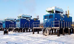

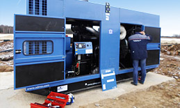
Описание FG Wilson DCP-10
Простой контроллер серии FG Wilson DCP-10 для управления и мониторинга одиночных генераторных установок обеспечивающий ручной и дистанционный запуск.
Настройка параметров контроллера проводится при помощи кнопок на передней панели или при помощи ПК через USB-интерфейс (DCP-10)
Версия DCP-10 в отличии от DCP-20 не имеет следующих функций: измерение мощности ДГУ, обмен через RS232, RS485, USB. Панель стандартно применяется на жидкостных ДГУ FG Wilson мощностью не более 220 кВА.
Возможности контроллера FG Wilson DCP-10:
- Трехфазный вольтметр
- Счетчик моточасов
- LCD экран
- Автозапуск
- Защита от неудачного запуска
- Защита от низкого давления и от высокой температуры двигателя
- Защита пониженных и повышенных оборотов двигателя
- разъем мини-USB
Обзор марки FG Wilson
Мы успешно реализуем энергетические решения уже 20 лет и накопили опыт решения самых сложных задач
Мы обладаем собственной мобильной службой сервиса и ремонта оборудования
Наш склад — это более тысячи наименований оригинальных запчастей и различных расходных элементов
Все наши решения защищены и проверены одной из крупнейших СРО. Ответственность застрахована
Источник
Панель управления dcp 10 схема подключения


Панель управления Wilson DCP-10
Серия DCP от компании FG Wilson включает в себя модель цифровых контроллеров DCP-10 применение которого максимально увеличивает безопасность работы генераторных установок, и предоставляет возможности эффективного мониторинга, контроля и управления системой атомного энергоснабжения.
Отличительной особенностью данного устройства является интуитивно понятный интерфейс системы управления, что значительно облегчает эксплуатацию генератора и предоставляет простые возможности получения наиболее важной диагностической информации. Взаимодействие с пользователем осуществляется на специальном ЖК-дисплее и при помощи светодиодных индикаторов с простыми и понятными графическими символами, благодаря чему освоить работы с контроллером DCP-10 легко и быстро может любой человек.
Основные преимущества данных систем:
- интуитивно понятное, простое управление;
- наличие всех необходимых встроенных систем измерения основных параметров работы и сети;
- все основные диагностические параметры и другая информация отображается на ЖК-дисплее или посредством светодиодных индикаторов;
- простая настройка основных параметров при помощи компьютера;
- встроенный модель управления автозапуском;
- длительный срок беспроблемной эксплуатации даже в самых жестких условиях.
Основные характеристики:
- возможность настройки основных параметров при помощи компьютера через обычное USB-соединение, а также в ручном режиме при помощи кнопок на передней панели устройства;
- встроенная система оперативного измерения реального напряжения в каждый момент времени;
- встроенная система постоянного мониторинга работы двигателя генератора и значения переменного тока;
- наличие отдельных кнопок Работа/Авто со специальными светодиодными индикаторами;
- интегрированная система защиты от пониженного или повышенного напряжения;
Источник
Control Panel Range
24 Pages

Catalog excerpts

FG Wilson Control Systems

Contents 1002T Analogue Control Panel FG Wilson DCP-10 and DCP-20 Digital Control Panels PowerWizard 1.1, 1.1+ and 2.1 Digital Control Panels PowerWizard Remote Monitoring Options PowerWizard Remote Monitoring and Control Options easYgen – 2500 Synchronising Control Panel easYgen – 3200 Synchronising Control Panel easYgen Control Panel Options – NetBiter FGW200 easYgen Control panel Options – I/O Expansion Module Load Transfer Panels CTI Panel Features ATI Panel Features Features and Options

FG Wilson Control Systems Putting You in Control Whatever your power requirements, FG Wilson can provide a control system to suit your needs. Our generator set experts design and validate FG Wilson control systems to optimise your generator set performance and put you in control. All FG Wilson control panels are compact, versatile and easy to use. Our comprehensive range includes key-start analogue control panels for straightforward functionality and reliability; digital control panels suitable for use in mains failure applications, providing advanced metering, protection and diagnostics;.

Analogue Control Panel The 1002T Control Panel is equipped with all the necessary generator set instrumentation and protection devices, whilst providing the straightforward functionality and reliability of a key-start panel. 1002T Benefits • Simplified monitoring of generator set conditions at a glance • eavy duty, reliable industrial push buttons and H switches • Visual individual warning and shutdowns through LED’s • Universal pictorial fault lamp indicators Analogue metering: voltmeter, ammeter, hours-run counter, combined frequency and tachometer 7 position voltmeter phase selector.

FG Wilson DCP Digital Control Panels The FG Wilson DCP range allows you to monitor and control your generator set with ease, providing important diagnostic information whilst ensuring your unit operates within safe parameters. FG Wilson DCP digital control panels, provide simple, intuitive menu navigation and control of your generator set operations. Key information is displayed via the LCD screen and LED’s using universally recognised symbols, eliminating the need for complex instructions or language settings. FG Wilson DCP-10 and DCP-20 Benefits • Automatic start control module •.

PowerWizard Digital Control Panels PowerWizard – Providing safe control of your generator set The FG Wilson PowerWizard range of digital control panels, combine straightforward menu navigation with advanced metering and protection technology. They are used in automatic mains failure applications in conjunction with transfer panels. Our PowerWizard range allows you to monitor and control your generator set with ease, whilst ensuring your unit operates within safe parameters and provides important diagnostic information when needed. PowerWizard 1.1, 1.1+ and 2.1 Benefits • Robust electronics.

PowerWizard Remote Monitoring Options Remote Monitoring The PowerWizard Annunciator is a 16-channnel display unit for remotely monitoring the status of FG Wilson generator sets at a distance of up to 240 metres. The Annunciator communicates via the CAN 2 data link which comes as standard on generator sets fitted with the PowerWizard 2.1 Control Panel. Each of the 16 channels on the Annunciator has two B LEDs to display status and alarm signals directly from the PowerWizard 2.1 Control Panel on the generator set. The pre-set channels linked to each LED display can be individually configured.

Remote Monitoring and Control Options Remote Monitoring and Control The FG Wilson Communications Interface Module and Software Package allows operators to monitor and control all generator set functions from a virtual control panel on their PC. Depending on the operator’s distance from the generator set and the type of connection available to link to the generator set, two options are offered: • or distances up to 1,000 metres, where it is convenient F to have a hard-wired connection, a generator set can be monitored using the Communications Interface Module and Software Package on the.

easYgen–2500 Synchronising Control Panel The easYgen-2500 offers industry leading power management and control The easYgen-2500 is a generator set-to-set controller for paralleling and load sharing applications of up to 16 generator sets. A special feature of the easYgen-2500 is the enhanced load sharing system. This provides advanced generator load dependent start / stop functionality with automatic generator set selection to ensure optimal system efficiency. easYgen–2500 Benefits • Capable of set-to-set synchronising for up to 16 generator sets • User friendly interface • Easy system.
DPC Cable Service Port RJ45 Loadshare Line • 16 Digital Inputs • 16 Digital Outputs Voltage Biasing • 3 phase true r.m.s. generator set current / power • 1 speed input (magnetic / switching) • 10 configurable discrete alarm inputs • ive configurable analogue inputs F • our configurable analogue outputs F (+/– 10 V, +/– 20 mA, PWM; configurable) • Two CAN bus interface (load share, Toolkit) • 11 Relay Outputs Isolated • RS485 Modbus interface • ervice Port S (RS232 – Woodward DPC cable required) Frequency Biasing Engine • Over / under speed • attery over / under voltage B • peed / frequency.
Synchronising Control Panel The easYgen-3200 offers industry leading power management and control The easYgen-3200 is a versatile control unit, incorporating all the features of the easYgen-2500 including enhanced load sharing, and is adaptable to every application. Typical applications include co-generation, standby, AMF, peak shaving, import / export or distributed generation. This control panel is suitable for synchronising up to 32 generator sets running in island mode, mains parallel and multiple unit mains parallel operations. Capable of generator set-to-set, set-to-mains and multiple.
Источник
ПАНЕЛЬ УПРАВЛЕНИЯ WILSON DCP-10
Серия DCP от компании FG Wilson включает в себя модель цифровых контроллеров DCP-10 применение которого максимально увеличивает безопасность работы генераторных установок, и предоставляет возможности эффективного мониторинга, контроля и управления системой атомного энергоснабжения. Отличительной особенностью данного устройства является интуитивно понятный интерфейс системы управления, что значительно облегчает эксплуатацию генератора и предоставляет простые возможности получения наиболее важной диагностической информации. Взаимодействие с пользователем осуществляется на специальном ЖК-дисплее и при помощи светодиодных индикаторов с простыми и понятными графическими символами, благодаря чему освоить работы с контроллером DCP-10 легко и быстро может любой человек.
Особенности:
- интуитивно понятное, простое управление;
- наличие всех необходимых встроенных систем измерения основных параметров работы и сети;
- все основные диагностические параметры и другая информация отображается на ЖК-дисплее или посредством светодиодных индикаторов;
- простая настройка основных параметров при помощи компьютера;
- встроенный модель управления автозапуском;
- длительный срок беспроблемной эксплуатации даже в самых жестких условиях.
Основные характеристики устройства:
- возможность настройки основных параметров при помощи компьютера через обычное USB-соединение, а также в ручном режиме при помощи кнопок на передней панели устройства;
- встроенная система оперативного измерения реального напряжения в каждый момент времени;
- встроенная система постоянного мониторинга работы двигателя генератора и значения переменного тока;
- наличие отдельных кнопок Работа/Авто со специальными светодиодными индикаторами;
- интегрированная система защиты от пониженного или повышенного напряжения.
Источник
FG Wilson DCP-10 Operation & User’s Manual
Information about FG Wilson DCP-10 User Guide:
Table of Contents / FG Wilson DCP-10 Owner’s Manual:
FG Wilson DCP-10 DCP-10 Page 2/27 2. Outline Dimension Drawings and Controller Wiring 2.1 Following Details: Module Dimensions W120mm×H102mm Panel Cutout W110mm×H92mm Thickness D48mm (without connection)
DCP-10 Page 6/27 4. Installation Guide 4.1 The cutout dimensional drawing installed on panel as above attached. The controller is fixed by 2 special fittings. The shock-proof equipment must be mounted if the e
DCP-10 Page 22/27 5 LOP switch low level is active 6 HET switch low level is active 7 Emergency stop low level is active 8 Remote start signal low level is active 9 Reserved low level is active 10 Gen Aux. Switch closed low level is active 11 Low
FG Wilson DCP-10 DCP-10 Page 26/27 10. Preparation before Starting the Controller 10.1 Make sure the controller is correctly installed to meet the ambient requirements. 10.2 Confirm all wiring connections of the controller meet the correct electric sp
FG Wilson DCP-10 DCP-10 Page 9/27 Stop Failure: When cool down times out, the fuel relay opens and the timer for Stop delay begins. When it times out, if controller detects that the voltage and frequency of generator or oil pressure of engine are greater than the preset values, the Fail to stop LED illuminates and the LCD displays Fail to stop. NOTE: After stop failure, the contro
DCP-10 Page 15/27 7.2 Shutdown Alarm NOTE: (shutdown alarm failures immediately lock out the system and stop the Genset. The failure must be removed and the controller reset before restarting the Genset.) Shutdown Alarm / Description LCD Display START FAILURE: if engine does not fire after the pre
FG Wilson DCP-10 DCP-10 I The interpretation of the Symbol: WARNING: A WARNING indicates a potentially hazardous situation which, if not avoided, could result in death, serious personal injury or property damage. CAUTION: A CAUTION indicates a potential
DCP-10 Page 14/27 OVER CURRENT: if any phase output current of generator exceeds the “over current pre-alarm” after the safety-on timer has expired, common failure LED indicator flashes. For example, “over current pre-alarm” preset as: 850A, when any phase ou
DCP-10 II WARNING: Read this entire manual pertaining to the work to be performed before installing, operating, or servicing this controller. Practice all plant and safety instru
FG Wilson DCP-10 DCP-10 Page 23/27 9. LCD Display and Menu System Using a backlit TN type LCD to display data and information. After pressing any push button the backlight will automatically turn off in a preset time. In normal operating status, you can set the page scroll time to circularly display each page of measuring data. Press “ ” manually scrolls to view each measuring data. When failure occurs, LCD displays the corre
DCP-10 Page 21/27 Datcon: Murphy: PT100: Pre-set 1: Pre-set 2: Pre-set 3: Pre-set 4: Type 12: :: : 8.7 The optional items for configurable input: Code Optional Function NOTE 0 not used 1 Pre-alarm (active immediately) low level is active 2 Shutdown Alarm(active immediately) low level is active 3 Pre-alarm (active after safety-on delay
FG Wilson DCP-10 DCP-10 Page 4/27 2.3 Typical Wiring Diagram (12/24V) DC POWER CRANKFUEL CONFIG.OUTPUT LOAD M CONFIG. INPUT REMOTE START COOLANT TEMP. (OR TEMP. SWITCH) OIL PRESSURE (OR OIL SWITCH) DCP-10 Fuse protection with a rating of 0.5A must be provided externally to the Controller.
DCP-10 Page 12/27 6. Measure and Display Data Gen phase voltage L1-N L2-N L3-N Gen line voltage L1-L2 L2-L3 L3-L1 Generator current I1 I2 I3 Generator frequency Hz Engine speed RPM (signal derived from generator frequency) Engine oil pressure BAR / PSI (signal from engine LOP sensor) Engine coolant temperature ℃/℉ (signal from engine HET sensor) Battery voltage Vdc
DCP-10 Page 13/27 7. Pre-alarm and Shutdown Alarm 7.1 Pre-alarm (Warning) NOTE: (Pre-alarms are non-critical failure conditions and do not affect the operation of the generator system, they serve for drawing the operators’ attention to
FG Wilson DCP-10 DCP-10 Page 8/27 NOTE: While cranking, engine ignites. The start motor will power off when the output frequency of generator reaches the preset value (configurable crank cutout value), or if there are one of the following conditions occur: A. Generator’s voltage reaches 80% of rated voltage; B. Cranking time’s up, C. LOP switch is opened and the delay time’s up. D. Oil pressure
FG Wilson DCP-10 DCP-10 Page 5/27 3. Panel Operation The operation panel consists of 3 sections: LCD display indicating measurement parameters, LED indicator for common failure, and push buttons for Genset and selection of control modes. The LCD circularly displays different measuring para
DCP-10 Page 1/27 1. Description The DCP-10 is an Automatic Controller for generator. When running in “AUTO” mode, it starts the Genset after receiving remote start signal and on failure automatically stops the Genset. The generator’s controlling procedure and protection parameters can be modified, which fully meets the Genset’s requirements of automa
DCP-10 Page 19/27 8.5 Calibration Menu: NO. Items Preset Value Range 5.1 GEN. V1 offset ±10.0% 5.2 GEN. V2 offset ±10.0% 5.3 GEN. V3 offset ±10.0% 5.4 Current I1 offset ±10.0% 5.5 Current I2 offset ±10.0% 5.6 Current I3 offset ±10.0% 5.7 Pressure offset
DCP-10 Page 24/27 9.2 Setting running parameters For example: (setting CT ratio at 1000/5, then CT should be configured as 200) Operation Description Press and hold “ ” 2sec, enter into parameters setting menu, then LCD displays: press “ ”, then LCD displays: Press “ ”, prompted enter password, then LCD displays: Press “ ” or �
FG Wilson DCP-10 DCP-10 Page 7/27 5. Control and Operation Instruction 5.1 Operation Mode Setting: The controller has 2 modes: AUTO and MANUAL. Operation Description Press and hold the “AUTO” button for 2sec, the LED above the button is illuminated; the controller i
FG Wilson DCP-10 DCP-10 Page 11/27 5.7 Flow chart for start and stop T1- start delay T2- crank time T3- pre-heat time T4- safety-on delay T5- idle time T6- stop delay NOTE: If T4 is longer than T5, low oil pressure protection is ignored during T5. If T4 is shorter than T5, low oil pressure protection becomes effe
FG Wilson DCP-10 DCP-10 Page 17/27 8. Parameters Setting 8.1 System Parameters: NO. Items Preset Value Range 1.1 CT ratio 100 1-2000 1.2 VT ratio 1.0 1.0-100.0 1.3 Rated ph-voltage 220 45-9999Vac 1.4 AC voltage 2 1,3 (3 for 3 phase 4 wire, 1 for signal phase 2 wire) 1.5 Startup mode 0 0-1 / 0 (MAN) / 1 (AUTO) 1.6 Oil pressure unit 0 0-1 (0-BAR,1-PSI) 1.7 Tempera
FG Wilson DCP-10 DCP-10 Page 20/27 Datcon 7 bar: Murphy 7 bar: Pre-set 1: Pre-set 2: Pre-set 3: Pre-set 4: Type 11: :: : HET sensor parameter addendum: VDO 120℃ ℃℃ ℃: VDO 150℃ ℃℃ ℃: P(Bar) 0.0 0.7 1.4 2.1 2.8 3.4 4.1 4.8 5.5 6.2 6.9 P(PSI) 0 10.0 20.0 30.0 40.0 50.0 60.0 70.0 80.0 90.0 1
FG Wilson DCP-10 DCP-10 Page 3/27 2.2 Terminal Connections: Pin no. Function Description Signal Dim 1 GEN. V L1-N input 0-300Vac 1mm² 2 GEN. V L2-N input 0-300Vac 1mm² 3 GEN. V L3-N input 0-300Vac 1mm² 4 GEN. Neutral 1mm² 5 Not used 6 Not used 7 I1 Gen current input 0-5A 2.
FG Wilson DCP-10 DCP-10 Page 25/27 For example: (resume parameters of controller to factory default) Operation Description Press and hold “ ” 2sec, enter into parameter settings menu, then LCD displays: Press “ ” 8 times, then LCD displays: press “ ” prompted enter password, then key in password: (2213)
FG Wilson DCP-10 DCP-10 Page 18/27 8.3 Engine Parameters: NO. Items Preset Value Range 3.1 Pair of poles 2 1-4 3.2 Fuel mode 0 0-1 / 0(NC) / 1 (NO) 3.3 T-sensor type 12 0-15 / 0 (not used) 3.4 P-sensor type 11 0-15 / 0 (not used) 3.5 Start delay 10S 0-300 S 3.6 Crank attem
Compatible Documentation:
Controller Operating manual (Reflexomat RS 90/1, #72ACEW)
Источник
Manual DCP - 10 Genset Controller DCP-10 I The interpretation of the Symbol: WARNING: A WARNING indicates a potentially hazardous situation which, if not avoided, could result in death, serious personal injury or property damage. CAUTION: A CAUTION indicates a potentially hazardous situation which, if not avoided, could result in damage to equipment or property. NOTE: A NOTE provides other helpful information that does not fall under the warning or caution categories. DCP-10 II WARNING: Read this entire manual pertaining to the work to be performed before installing, operating, or servicing this controller. Practice all plant and safety instructions and precautions. Failure to follow instructions can cause personal injury and/or property damage. The engine or other type of prime mover should be equipped with an overspeed shutdown device to protect against runaway or damage to the prime mover with possible personal injury, loss of life, or property damage. The overspeed shutdown device must be totally independent of the prime mover control system. An over temperature or low pressure shutdown device may also be needed for safety, as appropriate. CAUTION—BATTERY CHARGING To prevent damage to a controller that uses an alternator or battery- charging device, make sure the charging device is turned off before disconnecting the battery from the system. Controllers contain static-sensitive parts. Observe the following precautions to prevent damage to these parts: Do not disassemble the rear back of controller or touch the components and conductors on a printed circuit board. DCP-10 III Contents 1. Description…………………………………………………………………………………………………… 2. Outline Dimension Drawings and Controller Wiring………………………………………………… 3. Panel Operation…………………………………………………………………………………………… 4. Installation Guide………………………………………………………………………………………… 5. Control and Operation Instruction……………………………………………………………………… 6. Measure and Display Data……………………………………………………………………………… 7. Pre-alarm and Shutdown Alarm………………………………………………………………………… 8. Parameter Settings……………………………………………………………………………………… 9. LCD Display and Menu System………………………………………………………………………… 10. Preparation before Starting the Controller…………………………………………………………… 11. Technical Specification………………………………………………………………………………… 1 2 5 6 7 12 13 17 23 28 27 DCP-10 Page 1/27 1. Description The DCP-10 is an Automatic Controller for generator. When running in “AUTO” mode, it starts the Genset after receiving remote start signal and on failure automatically stops the Genset. The generator’s controlling procedure and protection parameters can be modified, which fully meets the Genset’s requirements of automatic start, stop control and basic protection. The module displays fault conditions, operational status and related metering data on panel LCD. LCD has a backlight function so that the operator can read running parameters clearly even in the shadow. The controller has 2 modes: AUTO and MANUAL. Either can be chosen through the panel push button. Measures and displays generator’s output voltage, current, oil pressure, coolant temperature, frequency, DC source voltage, etc. True RMS measure of voltage and current, which ensures the data more accurate. Control the close/open of generator output switch. Equipped with built-in communication interface to configure parameters by PC. All connections of controller are by secure plug and socket, for ease and convenience to connect, move, maintain and replace the device. This manual is only suitable for DCP-10 Automatic control module, user must carefully read this manual first. DCP-10 Page 2/27 2. Outline Dimension Drawings and Controller Wiring 2.1 Following Details: Module Dimensions W120mm×H102mm Panel Cutout W110mm×H92mm Thickness D48mm (without connection) DCP-10 Page 3/27 2.2 Terminal Connections: Pin no. Function Description Signal Dim 1 GEN. V L1-N input 0-300Vac 1mm² 2 GEN. V L2-N input 0-300Vac 1mm² 3 GEN. V L3-N input 0-300Vac 1mm² 4 GEN. Neutral 1mm² 5 Not used 6 Not used 7 I1 Gen current input 0-5A 2.5mm² 8 I2 Gen current input 0-5A 2.5mm² 9 I3 Gen current input 0-5A 2.5mm² 10 Common port for current input 0-5A 2.5mm² 11 LOP sensor or switch signal LOP sensor (<2KΩ) 1mm² 12 HET sensor or switch signal HET sensor (<2KΩ) 1mm² 13 Configurable digital input signal 1 low level is active 1mm² 14 Configurable digital input signal 2 low level is active 1mm² 15 Configurable digital input signal 3 low level is active 1mm² 16 Charge excitation power output if not used, do not connect to negative 1mm² 17 Configurable relay output 1 N.O. contact, 3A/30Vdc 1mm² 18 Configurable relay output 2 N.O. contact, 3A/30Vdc 1mm² 19 Configurable relay output 3 N.O. contact, 3A/30Vdc 1mm² 20 +5V supply Max 100mA, 1mm² 21 Start (Crank) relay output N.O. contact, 3A/30Vdc 1mm² 22 Fuel solenoid relay output N.O. contact, 3A/30Vdc 1mm² 23 Battery supply (+B) 1mm² 24 Battery supply (-B) 12V/24V (8-35Vdc continuous) 1mm² DCP-10 Page 4/27 2.3 Typical Wiring Diagram (12/24V) DC POWER CRANKFUEL CONFIG.OUTPUT LOAD M CONFIG. INPUT REMOTE START COOLANT TEMP. (OR TEMP. SWITCH) OIL PRESSURE (OR OIL SWITCH) DCP-10 Fuse protection with a rating of 0.5A must be provided externally to the Controller. DCP-10 Page 5/27 3. Panel Operation The operation panel consists of 3 sections: LCD display indicating measurement parameters, LED indicator for common failure, and push buttons for Genset and selection of control modes. The LCD circularly displays different measuring parameters. When failure occurs, LCD displays the corresponding fault icon. LCD also has a backlight so that the operator can clearly read information day or night. After pressing any button the backlight will automatically turn off in a certain time. The LCD display and its control push buttons provide a friendly operation interface for the operator to conveniently read information and parameter setting. 3.1 Control buttons and LEDs Function Description Tag Scroll Button Enter into submenu / Modify / confirm modification / scroll menu to display. MUTE / LAMP TEST Button When failure occurs, alarm buzzer sounds. Pressing mute button will mute the sound. LCD displays mute icon. Press and hold mute button for 2sec, all LEDs illuminate simultaneously. AUTO Mode Button / LED The push button is used for selecting “AUTO mode”. When the controller is running in AUTO mode, the LED above the push button illuminated. The activation and deactivation of the “remote start signal input” controls the starting and stopping of the Genset. MAN Mode Button / LED The push button is used for selecting “manual mode”. When the controller is running in MANUAL mode, the LED above the push button illuminated. The Start and Stop push buttons control the starting and stopping of the Genset.. START / VALUE INCREASE “+” Push Button The push button is used for manually start the Genset .When the controller is in MANUAL mode, press this push button to start the generator. When in parameter setting mode, this push button is used to increase values. STOP / RESET / VALUE DECREASE “-” Push Button The push button is used for MANUALLY stops the Genset. When the controller is in MAN mode, press and hold this button more than 2sec to stop the Genset. If failure occurs, press this button, the shutdown alarm lockout can be cleared. When in parameter setting mode, this push button is used to decrease values. COMMEN FAILURE LED LED will flash when pre-alarm (Warning) occurs. LED will illuminate permanently when shutdown alarm occurs. DCP-10 Page 6/27 4. Installation Guide 4.1 The cutout dimensional drawing installed on panel as above attached. The controller is fixed by 2 special fittings. The shock-proof equipment must be mounted if the enclosure is mounted on Genset or other heavy vibrant device. A readily accessible disconnect device shall be incorporated external to the equipment. 4.2 Please refer to the above Typical Wiring Diagram 2.3 for connection. 4.3 Installation of engine LOP and HET sensors: 1211 Terminal 12 Battery negative (Genset enclosure) 11 Description Sensor Com. Port HET sensor/ temp switch LOP sensor/ LOP switch DCP-10 CAUTION: Pin no. “11” and “12” is for “LOP sensor or switch signal” and “HET sensor or switch signal” input respectively. Either switch or sensor can be chosen. When sensor is used, according to the actual situation, increase the cross section area of cable to reduce the cable resistance from controller to engine, which ensures the accuracy of measured values for both oil pressure and engine temperature. If both switches and sensors are required for oil pressure and engine temperature, connect Pin no. “11” and “12” as above, and connect 2 configurable inputs to the switches of oil pressure and temperature, then configure parameters by setting. DCP-10 Page 7/27 5. Control and Operation Instruction 5.1 Operation Mode Setting: The controller has 2 modes: AUTO and MANUAL. Operation Description Press and hold the “AUTO” button for 2sec, the LED above the button is illuminated; the controller is running in “AUTO” mode. Press and hold the “MAN” button for 2sec, the LED above the button is illuminated; the controller is running in “MAN” mode. NOTE: Only 1 mode can be selected from above 2 modes. 5.2 AUTO control Sequence: Controller is running in “AUTO” mode. First of all, one of configurable inputs must be defined as Remote Start Signal. When the remote start signal is active, the controller implements following procedure: The Start delay timer is activated, when it times out the Preheat relay output is energized (if preheat function selected), the timer starts. When it times out, the fuel relay output is energized, and operates the fuel solenoid of the engine. After 300ms delay, the start (crank) relay output is energized; the start motor engages and begins to crank. When the engine speed reaches the crank cutout RPM, the start relay output is de-energized and the safety-on delay starts. When the safety-on times out, if the controller detects that the parameters of the Genset such as voltage, frequency, oil pressure, coolant temperature are normal, and no other failure is detected this indicates the Genset has successfully started and running normally. The LCD displays the Genset Measuremen parameters. When the voltage and frequency of Generator is normal, Gen. Normal LED illuminates, the timer for Gen. On delay is activated, when it times out, GCB close/open relay closes,the transfer switch switches on Gen. The Gen Aux. Switch’s contact feeds back a signal to a configurable input on our controller. GCB closed LED illuminates. NOTE: When remote signal is active, the start-delay timer is activated. During this period, if remote start signal is inactive, the start delay timer terminates immediately; the controller will recovers to the original standby status. During cranking or idle period, if remote start signal is inactive, controller stops the start procedure and recovers to original standby status. DCP-10 Page 8/27 NOTE: While cranking, engine ignites. The start motor will power off when the output frequency of generator reaches the preset value (configurable crank cutout value), or if there are one of the following conditions occur: A. Generator’s voltage reaches 80% of rated voltage; B. Cranking time’s up, C. LOP switch is opened and the delay time’s up. D. Oil pressure switch is opened or oil pressure is higher than crank cutout value. E. Cutout P-delay time’s up. Controller can not implement crank procedure if the frequency of generator reaches the preset value (configurable cranking cutout value) or LOP switch is opened. CAUTION: To avoid damage to the start motor please make sure the generator’s voltage is higher than the measurable value of controller while cranking, since the crank cutout signal is sensed from the generator voltage and frequency. NOTE: Above control procedure, assumes that one of configurable inputs has been configured as Gen Aux. Switch Closed and connects the switch’s N.O. Aux. contact signal to this port. If you do not configure an input as Gen Aux. Switch Closed, then the GCB closed LED illuminates is only an indication that the GCB close/open relay should have been closed. If you have selected idle function, the idle relay will be closed at the same time as the crank relay is closed. The timers of idle and safety-on delay will begin counting down at the same time, and in priority to display the shorter one on the LCD, and the following procedure is the same as above. During the crank period, if the engine can not ignite and controller will not output start signal during crank rest, Fail to Start icon on LCD flashes at this time. Once crank rest timer times out the start relay energizes once again and will attempt to start engine again. The above procedure will be repeated until engine successfully ignites or reaches the preset number of crank attempt. However, if any shutdown alarm occurs during crank, controller will stop cranking immediately and only can be restarted after clearing failure and reset. Fail to Start: when the above procedure repeats again and again and reaches the preset number of crank attempt, the crank relay output is then de-energized. The failure LED illuminates and the LCD displays Fail to Start. CAUTION: If Fail to Start occurs, operator must check the whole Genset system to find out failure reason, only after clearing the failure can press “STOP/RESET” button to relieve fault lock out status, and restart the Genset. Generator shutdown sequence: When the remote start signal is deactivated, the timer for cool down is activated, When it times out, the fuel relay de-energizes, the timer for cool down is activated, DCP-10 Page 9/27 Stop Failure: When cool down times out, the fuel relay opens and the timer for Stop delay begins. When it times out, if controller detects that the voltage and frequency of generator or oil pressure of engine are greater than the preset values, the Fail to stop LED illuminates and the LCD displays Fail to stop. NOTE: After stop failure, the controller will not energize the crank relay output if the failure has not been removed and the controller reset. 5.3 MAN control sequence: Controller is in “MANUAL” mode. Generator starting sequence: Pressing “START” button the fuel relay energises, and operates the fuel solenoid of engine.After 300ms delay, the start relay output is energized, the start motor engages and begins to crank. When the engine speed reaches the crank cutout RPM, the start relay output is de-energized and the safety-on delay starts. When the safety-on times out, if the controller detects that the parameters of the Genset such as voltage, frequency, oil pressure and coolant temperature are normal, and no other failure is detected this indicates the Genset has successfully started and running normally. The LCD displays the Genset Measurement parameters. When generator is running normally, GCB close/open relay will not close automatically. Manually close the Gen switch, Gen is on load, the Gen Aux. Switch’s contact feeds back the signal to a configurable input on our controller, Gen. Normal LED illuminates. 5.4 The start and stop sequence of engine whose fuel solenoid is N. O. type: Start control sequence: During the starting sequence, the fuel relay of controller will not energize, fuel solenoid is no power, so no signal is required for fuel solenoid to activate. Stop control sequence: During the stopping sequence, the fuel relay energizes, fuel solenoid is on power and energizes, and the engine begins to stop. After a delay (same as stop delay) fuel relay de-energizes, disconnecting the supply for the fuel solenoid. Other control sequence is same as engine whose fuel solenoid is N. C. type. NOTE: When the controller is in “MANUAL” mode and Gen. Normal LED illuminates, you must define one configurable input as Gen Aux. Switch Closed and connect the switch’s N.O. Aux. contact signal to this port, otherwise the GCB closed LED will not illuminate. DCP-10 Page 10/27 5.5 Idle function: For idle function configure one of the configurable outputs as idle. Refer to the flow chart 5.7 for start and stop for idle control flows. 5.6 Preheat function: For Preheat function, configure one of the configurable outputs as Preheat. The controller has 3 selectable preheat control modes as below: Mode 1 — during preheat time, preheat relay output energizes. Mode 2 — during preheat time, preheat relay output energizes until the successful ignition. Mode 3 — during preheat time, preheat relay output energizes until safety-on delay times out. During crank period, the Preheat relay output will not energize in any of above modes. Refer to the flow chart 5.7 for start and stop for Preheat control flows. When the Preheat relay output energizes, LCD displays the icon of preheat operating status: DCP-10 Page 11/27 5.7 Flow chart for start and stop T1- start delay T2- crank time T3- pre-heat time T4- safety-on delay T5- idle time T6- stop delay NOTE: If T4 is longer than T5, low oil pressure protection is ignored during T5. If T4 is shorter than T5, low oil pressure protection becomes effective after T4 in T5. DCP-10 Page 12/27 6. Measure and Display Data Gen phase voltage L1-N L2-N L3-N Gen line voltage L1-L2 L2-L3 L3-L1 Generator current I1 I2 I3 Generator frequency Hz Engine speed RPM (signal derived from generator frequency) Engine oil pressure BAR / PSI (signal from engine LOP sensor) Engine coolant temperature ℃/℉ (signal from engine HET sensor) Battery voltage Vdc Genset Running hour Hour DCP-10 Page 13/27 7. Pre-alarm and Shutdown Alarm 7.1 Pre-alarm (Warning) NOTE: (Pre-alarms are non-critical failure conditions and do not affect the operation of the generator system, they serve for drawing the operators’ attention to an undesirable condition so they can remove it to ensure continuous running of the system. When Pre-alarms occur, the LED indicator flashes, but failure will not be locked out and the unit will not shutdown. Once the Pre-alarm failure is removed the Pre-alarm LED will automatically turn off.) Pre-alarm / Description LCD Display CHARGE FAILURE: After safety-on times up, if the charging voltage from the excitation contact of alternator is lower than the “charge V Pre-alarm”, the common failure LED indicator ( ) flashes, the LCD displays Charge failure icon: BATT. UNDER VOLT: if controller detects that battery voltage has fallen below the “Batt. Under volt”, common failure LED indicator flashes. For example, “Batt. Under volt” preset as: 23.6V, when battery voltage falls below this value, LCD flashing low value icon: BATT. OVER VOLT: if controller detects that battery voltage has exceeded the “Batt. Over volt”, common failure LED indicator flashes. For example, “Batt. Over volt” preset as preset as: 28.2V, when battery voltage exceeds this value, LCD flashing high value icon: LOW OIL PRESS: if controller detects that the engine oil pressure has fallen below the “Oil-P low preALM” after the safety-on timer expired, common failure LED indicator flashes. For example, “Oil-P low preALM” preset as: 2.2BAR, when engine oil pressure falls below this value, LCD flashing low value icon: HIGH TEMP: if controller detects that engine coolant temperature has exceeded the “high temp pre-alarm”, common failure LED indicator flashes. For example, “high temp pre-alarm” preset as: 95℃ ℃℃ ℃, when engine coolant temperature exceeds this value, LCD flashing high value icon: OVER SPEED: if engine speed exceeds the “Over SP preALM”, common failure LED indicator flashes. For example, “Over SP preALM” preset as: 1600RPM, when engine speed exceeds this value, LCD flashing high value icon: UNDER SPEED: if engine speed falls below the “Under SP preALM” after the safety-on timer has expired, common failure LED indicator flashes. For example, “Under SP preALM” preset as: 1440RPM, when engine speed falls below this value, LCD flashing low value icon: DCP-10 Page 14/27 OVER CURRENT: if any phase output current of generator exceeds the “over current pre-alarm” after the safety-on timer has expired, common failure LED indicator flashes. For example, “over current pre-alarm” preset as: 850A, when any phase output current of generator exceeds this value, LCD flashing high value icon for corresponding phase: GEN. OVER VOLT: if controller detects that any phase output voltage of generator has exceeded the “GEN-V over preALM”after the safety- on timer has expired, common failure LED indicator flashes. For example, “Rated ph-voltage” preset as: 220V, “GEN-V over preALM” preset as: 115%, when any phase output voltage of generator exceeds this value, LCD flashing high value icon for corresponding phase: GEN. UNDER VOLT: if controller detects that any phase output voltage of generator has fallen below the “GEN-V under preALM”after the safety-on timer has expired, common failure LED indicator flashes. For example, “Rated ph-voltage” preset as: 220V, “GEN-V under preALM”preset as: 90%, when any phase output voltage of generator falls below this value, LCD flashing low value icon for corresponding phase: LOW FUEL LEVEL: If a configurable input has been defined as low fuel level, when the input signal is active, common failure LED indicator flashes, LCD displaying low fuel level icon: AUXILIARY PRE-ALARM: if a configurable input is defined as pre-alarm, when the input signal is active, common failure LED indicator flashes. LCD displaying Aux. pre-alarm icon: NOTE: To make “low oil pressure” and “high temperature” pre-alarm active, you must use LOP sensor and HET sensor, if you only use LOP and HET switches, both pre-alarms are inactive. NOTE: Controller continuously detects battery voltage during standby and Battery Low/High Voltage pre-alarms are active. Battery Low Voltage pre-alarm is inactive during cranking. CAUTION: Under the period of safety-on delay, some pre-alarms (e.g.: under speed, low voltage and low oil pressure) are inactive, the safety-on delay must be carefully and properly set to make Genset have full protection. DCP-10 Page 15/27 7.2 Shutdown Alarm NOTE: (shutdown alarm failures immediately lock out the system and stop the Genset. The failure must be removed and the controller reset before restarting the Genset.) Shutdown Alarm / Description LCD Display START FAILURE: if engine does not fire after the preset number of crank attempt has been made, the Shutdown alarm LED illuminates. LCD displays “start failure” icon: STOP FAILURE: if engine does not stop after the stop delay expired, the Shutdown alarm LED illuminates. LCD displays stop failure icon: EMERGENCY STOP: Configure a configurable input as emergency stop, when the input signal is active, controller immediately stops all relay control outputs except alarm,Genset is shut down, the Shutdown alarm LED illuminates, LCD displays emergency stop icon: LOW OIL PRESS: if controller detects that the oil pressure level still falls below “Oil-P low Alarm” or LOP switch closes after the safety-on timer has expired, engine stops immediately, the Shutdown alarm LED illuminates. LCD displays low oil pressure icon: ENGINE HIGH TEMP: if controller detects that engine coolant temperature has exceeded the “Coolant Alarm” or HET switch closes, engine stops immediately, the Shutdown alarm LED illuminates. LCD displays high temperature icon: OVER SPEED: if controller detects that engine speed exceeds “Over SP Alarm”, engine stops immediately, the Shutdown alarm LED illuminates. LCD displays over speed icon: OVER CURRENT: After safety-on delay time out, if controller detects that any phase output current of generator exceeds the “over current alarm”, the Genset will be shut down immediately, the Shutdown alarm LED illuminates. GEN. OVER VOLT: After safety-on delay times out, if controller detects that one of the phase voltage exceeds the“GEN-V over Alarm”, the engine will be shut down immediately, the Shutdown alarm LED illuminates. GEN. UNDER VOLT: After safety-on delay times up, if controller detects that any phase output voltage is lower than the “Vac low alarm”, the engine will be shut down immediately, common failure LED illuminates. AUXILIARY FAILURE: If a configurable input has been defined as Shutdown Alarm, when the input signal is active, common failure LED illuminates. LCD displays Aux. shutdown alarm icon: DCP-10 Page 16/27 Code Table for Failure: Name Code Name Code CHARGE FAILURE ENGINE HIGH TEMP BATT. UNDER VOLT OVER SPEED BATT. OVER VOLT UNDER SPEED START FAILURE OVER CURRENT STOP FAILURE GEN. OVER VOLT EMERGENCY STOP GEN. UNDER VOLT LOW OIL PRESS P-SENSOR OPEN NOTE: Engine speed signal is derived from the frequency of generator output voltage, it is used for control and failure protection parameters, for the convenience of user, some data is expressed by RPM, RPM = Hz * 60 / pair of poles. While the Genset is running, if there are high coolant temperature, low oil pressure or over speed failure occurs, the controller will shutdown it immediately without delay. During the cool down period, if there is low oil pressure failure, the alarm will be active no matter if there is idle function. CAUTION: During the period of safety-on delay, low oil pressure protection is inactive. To avoid starting an engine with no oil, you must make sure the oil levels are normal and the safety-on delay shall be carefully and properly set for the first commissioning. DCP-10 Page 17/27 8. Parameters Setting 8.1 System Parameters: NO. Items Preset Value Range 1.1 CT ratio 100 1-2000 1.2 VT ratio 1.0 1.0-100.0 1.3 Rated ph-voltage 220 45-9999Vac 1.4 AC voltage 2 1,3 (3 for 3 phase 4 wire, 1 for signal phase 2 wire) 1.5 Startup mode 0 0-1 / 0 (MAN) / 1 (AUTO) 1.6 Oil pressure unit 0 0-1 (0-BAR,1-PSI) 1.7 Temperature unit 0 0-1 (0-℃,1-℉) 1.8 Comm. Address 1 1-247 1.9 Default settings 1.10 On-line update 1.11 Scroll time 0S 0-10 S / 0 (not used) NOTE: For 1.5 Startup Mode, When parameter is configured as “1”, the controller will be in AUTO mode when it is powered on; When parameter is configured as “0”, the controller will be in Manual mode when it is powered on. After the oil pressure and temperature units changed, the corresponding failure alarm value must be reset according to actual situation. Engine speed is calculated by the number of “pair of poles”. RPM=Hz * 60 / pair of poles, when rated frequency is 50 Hz, if pair of poles set as “2”, then running speed is 1500 RPM, if pair of poles set as “1” , then running speed is 3000 RPM. 8.2 Generator Parameters: NO. Items Preset Value Range 2.1 V under Alarm 0 20-200% / 0 (not set) 2.2 V under preALM 90% 20-200% / 0 (not set) 2.3 V over preALM 115% 20-200% / 9999 (not set) 2.4 V over Alarm 9999 20-200% / 9999 (not set) 2.5 Hz low alarm 45.0Hz 10.0-100.0Hz / 0 (not set) 2.6 Hz high alarm 57.0Hz 10.0-100.0Hz / 999.9 (not set) 2.7 Over current pre-alarm 100% 0-200% 2.8 Over current alarm 150% 0-200% 2.9 Over current action 0 0-1 (0- electrical tripping, 1-shutdown alarm) 2.10 Alarm delay 10S 0-600 S 2.11 Gen. On delay 5S 1-9999 S 2.12 GCB opening delay 5S 1-9999 S DCP-10 Page 18/27 8.3 Engine Parameters: NO. Items Preset Value Range 3.1 Pair of poles 2 1-4 3.2 Fuel mode 0 0-1 / 0(NC) / 1 (NO) 3.3 T-sensor type 12 0-15 / 0 (not used) 3.4 P-sensor type 11 0-15 / 0 (not used) 3.5 Start delay 10S 0-300 S 3.6 Crank attempt 3 times 1-10 times 3.7 Crank time 5S 0-30 S 3.8 Crank rest 10S 0-300 S 3.9 Crank cutout RPM 300RPM 1-9999 RPM 3.10 Crank cutout Oil-P 1.0BAR 0.1-150.0BAR/999.9(not set) 3.11 cutout P-delay 0 1-60 S / 0(not set) 3.12 Idle delay 0 0-9999 S 3.13 Preheat delay 3S 0-300 S 3.14 Preheat mode 1 1-3 3.15 Safety-on delay 10S 0-600 S 3.16 Cool down delay 300S 0-600 S 3.17 Stop delay 20S 0-60 S 3.18 Under SP Alarm 0RPM 0-9999 RPM / 0 (not set) 3.19 Under SP preALM 1440RPM 0-9999 RPM / 0 (not set) 3.20 Over SP preALM 1600RPM 1-9999 RPM / 9999 (not set) 3.21 Over SP Alarm 1710RPM 1-9999 RPM / 9999 (not set) 3.22 Oil-P low Alarm 1.1BAR 0-45.0 BAR 3.23 Oil-P low preALM 1.4BAR 0-45.0 BAR 3.24 Coolant preALM 92℃ 70-320℃ / 9999 (not set) 3.25 Coolant Alarm 100℃ 70-320℃ / 9999 (not set) 3.26 Batt. Undervolt. 8.0V 1.0-25.0V / 0 (not set) 3.27 Batt. overvolt. 28.0V 1.0-35.0V / 99.9 (not set) 3.28 charge V Pre-alarm 8.0V 1.0-25.0V / 0 (not set) 8.4 Configurable Inputs and Outputs: NO. Items Preset Value Range 4.1 Configurable input 1 8 0-12 (define code as 8.7) 4.2 Configurable input 2 7 0-12 (define code as 8.7) 4.3 Configurable input 3 12 0-12 (define code as 8.7) 4.4 Input 1 delay 2S 0-60 S 4.5 Input 2 delay 2S 0-60 S 4.6 Input 3 delay 2S 0-60 S 4.7 Configurable relay 1 2 0-80 (define code as 8.8) 4.8 Configurable relay 2 3 0-80 (define code as 8.8) 4.9 Configurable relay 3 5 0-80 (define code as 8.8) NOTE: D-Input Delay is only for 1 to 4 codes in 8.7. DCP-10 Page 19/27 8.5 Calibration Menu: NO. Items Preset Value Range 5.1 GEN. V1 offset ±10.0% 5.2 GEN. V2 offset ±10.0% 5.3 GEN. V3 offset ±10.0% 5.4 Current I1 offset ±10.0% 5.5 Current I2 offset ±10.0% 5.6 Current I3 offset ±10.0% 5.7 Pressure offset ±10.0% 5.8 Temperature offset ±10.0% 5.9 Batt. V offset ±10.0% 8.6 The optional items for P/T-sensor: Code The brand model of LOP sensor The brand model of HET sensor 0 not used not used 1 close for low oil pressure close for high temperature 2 open for low oil pressure open for high temperature 3 VDO 5 bar VDO 120 ℃ 4 VDO 10 bar VDO 150 ℃ 5 Datcon 7 bar Datcon 6 Murphy 7 bar Murphy 7 Pre-set 1 PT100 8 Pre-set 2 Pre-set 1 9 Pre-set 3 Pre-set 2 10 Pre-set 4 Pre-set 3 11 configured by user Pre-set 4 12 configured by user NOTE: When the controller leaves factory, the optional types and functions of LOP sensor and HET sensor have been preset as the above table. If the using sensor is not listed in this table, the user can select “configurable”, and write sensor parameters to controller via software. LOP sensor parameter addendum: VDO 5 bar: VDO 10 bar: P(Bar) 0.0 0.5 1.0 1.5 2.0 2.5 3.0 3.5 4.0 4.5 5 P(PSI) 0 7.3 14.5 21.8 29.0 36.3 43.5 50.8 58.0 65.3 72.5 R(Ω) 11 29 47 65 82 100 117 134 151 167 184 P(Bar) 0.0 1.0 2.0 3.0 4.0 5.0 6.0 7.0 8.0 9.0 10.0 P(PSI) 0 14.5 29.0 43.5 58.0 72.5 87.0 101.5 116.0 130.5 145.0 R(Ω) 10 31 52 71 90 106 124 140 155 170 184 DCP-10 Page 20/27 Datcon 7 bar: Murphy 7 bar: Pre-set 1: Pre-set 2: Pre-set 3: Pre-set 4: Type 11: :: : HET sensor parameter addendum: VDO 120℃ ℃℃ ℃: VDO 150℃ ℃℃ ℃: P(Bar) 0.0 0.7 1.4 2.1 2.8 3.4 4.1 4.8 5.5 6.2 6.9 P(PSI) 0 10.0 20.0 30.0 40.0 50.0 60.0 70.0 80.0 90.0 100.0 R(Ω) 240 200 165 135 115 95 78 63 48 35 25 P(Bar) 0.0 0.7 1.4 2.1 2.8 3.4 4.1 4.8 5.5 6.2 6.9 P(PSI) 0 10.0 20.0 30.0 40.0 50.0 60.0 70.0 80.0 90.0 100.0 R(Ω) 240 205 171 143 123 103 88 74 60 47 33 P(Bar) 0.0 1.0 2.0 3.0 4.0 5.0 6.0 7.0 8.0 9.0 10.0 P(PSI) 0 14.5 29.0 43.5 58.0 72.5 87.0 101.5 116.0 130.5 145.0 R(Ω) 15 31 49 66 85 101 117 132 149 164 178 P(Bar) 0.0 1.0 2.0 3.0 4.0 5.0 6.0 7.0 8.0 9.0 10.0 P(PSI) 0 14.5 29.0 43.5 58.0 72.5 87.0 101.5 116.0 130.5 145.0 R(Ω) 30 41 65 88 110 115 145 150 172 185 190 P(Bar) 0.0 1.7 3.4 5.2 6.9 8.6 10.3 P(PSI) 0 25 50 75 100 125 150 R(Ω) 21 36 52 72 84 100 120 P(Bar) 0.0 1.0 2.0 3.0 4.0 5.0 6.0 6.5 7.0 8.0 9.0 P(PSI) 0 14.5 29.0 43.5 58.0 72.5 87.0 94.3 101.5 116.0 130.5 R(Ω) 251 195 155 127 107 88 72 65 61 54 48 P(Bar) 0.0 0.5 1.0 1.5 2.0 2.5 3.0 3.5 4.0 4.5 R(Ω) 21.5 25 27.6 30.2 33.5 36.8 40.3 43.2 46.9 50.6 V 0.48 0.55 0.6 0.65 0.71 0.77 0.83 0.88 0.94 1.0 T(℃) 40 50 60 70 80 90 100 110 120 130 140 T(℉) 104 122 140 158 176 194 212 230 248 266 284 R(Ω) 291 197 134 97 70 51 38 29 22 18 15 T(℃) 50 60 70 80 90 100 110 120 130 140 150 T(℉) 122 140 158 176 194 212 230 248 266 284 302 R(Ω) 322 221 155 112 93 62 47 37 29 23 19 DCP-10 Page 21/27 Datcon: Murphy: PT100: Pre-set 1: Pre-set 2: Pre-set 3: Pre-set 4: Type 12: :: : 8.7 The optional items for configurable input: Code Optional Function NOTE 0 not used 1 Pre-alarm (active immediately) low level is active 2 Shutdown Alarm(active immediately) low level is active 3 Pre-alarm (active after safety-on delay) low level is active 4 Shutdown Alarm(active after safety-on delay) low level is active T(℃) 40 50 60 70 80 90 100 110 120 130 140 T(℉) 104 122 140 158 176 194 212 230 248 266 284 R(Ω) 900 600 400 278 200 141 104 74 50 27 4 T(℃) 40 50 60 70 80 90 100 110 120 130 140 T(℉) 104 122 140 158 176 194 212 230 248 266 284 R(Ω) 1029 680 460 321 227 164 120 89 74 52 40 T(℃) -100 -50 0 20 40 60 80 100 150 200 300 T(℉) -148 -58 32 68 104 140 176 212 302 392 572 R(Ω) 60 81 100 108 116 123 131 139 157 176 212 T(℃) 20 30 40 50 60 70 80 90 100 110 120 T(℉) 68 86 104 122 140 158 176 194 212 230 248 R(Ω) 900 600 420 282 152 113 86 62 48 40 30 T(℃) 30 50 60 70 80 90 100 110 120 T(℉) 86 122 140 158 176 194 212 230 248 R(Ω) 980 400 265 180 125 90 65 50 38 T(℃) 20 30 40 50 60 70 80 90 100 110 120 T(℉) 68 86 104 122 140 158 176 194 212 230 248 R(Ω) 805 540 380 260 175 118 83 58 42 30 21 T(℃) 28 35 40 50 60 70 80 90 95 98 T(℉) 82 95 104 122 140 158 176 194 203 208 R(Ω) 579 404 342 250 179 136 103 77 67 63 T(℃) 150 130 110 90 80 70 50 25 0 0 R(Ω) 6.9 10.8 17.7 30.6 41.1 56.3 111.8 300 964.4 964.4 DCP-10 Page 22/27 5 LOP switch low level is active 6 HET switch low level is active 7 Emergency stop low level is active 8 Remote start signal low level is active 9 Reserved low level is active 10 Gen Aux. Switch closed low level is active 11 Low fuel level low level is active 12 Lamp test low level is active 8.8 The optional items for configurable output: Code Failure Type Define Code Failure Type Define 0 Not used 1 Over current tripping 2 Alarm 3 Pre-alarm 4 Idle 0 (N.C.) 5 Preheat 6 Speed up 7 Reserved 8 Fuel pump control 9 Running 10 System in AUTO mode 11 Reserved 12 System in MAN mode 13 Reserved 14 Idle 1 (N.O.) 15 Reserved 16 GCB failure (within 5s) 17 Fail to start NOTE: If define one configurable relay as Speed up, the relay will close after the engine has successfully started. If there is idle function, the relay will close after idle timer times out. DCP-10 Page 23/27 9. LCD Display and Menu System Using a backlit TN type LCD to display data and information. After pressing any push button the backlight will automatically turn off in a preset time. In normal operating status, you can set the page scroll time to circularly display each page of measuring data. Press “ ” manually scrolls to view each measuring data. When failure occurs, LCD displays the corresponding failure icon. Press and hold “ ” button 2sec to enter into parameters setting menu, then use “ ” or “ ” to scroll page, press “ ” again to select the required modify item, press “ ” or “ ”, LCD displays 0 0 0 0 when prompted to enter password, then use “ ” or “ ” to modify the first digital value, press “ ” move to modify the next one, after this, the first digital value will be displayed as “H”. Press “ ” to confirm after the password is set as 2213, then you can modify parameters. Otherwise it will prompt to key in password again. Press and hold “ ” for more than 2sec to quit parameters setting mode after finishing configuration. 9.1 Static LCD displays Controller is in standby status, circularly displays each measuring data: → →→ → Controller is normally running, circularly displays each measuring data: → →→ → → →→ → → →→ → → →→ → NOTE: When T-sensor or P-sensor is set as “not used”, LCD will not display related measuring data. DCP-10 Page 24/27 9.2 Setting running parameters For example: (setting CT ratio at 1000/5, then CT should be configured as 200) Operation Description Press and hold “ ” 2sec, enter into parameters setting menu, then LCD displays: press “ ”, then LCD displays: Press “ ”, prompted enter password, then LCD displays: Press “ ” or “ ” prompted enter password: (2213), then press “ ” again, press “ ” or “ ” to change parameter, change at 200, then LCD displays: Press “ ” to confirm,then press “ ”, then LCD displays: Press “ ” again to quit, or press and hold “ ” more than 2s also can quit, then LCD displays: For example: (setting controller crank attempt at 2) Operation Description Press and hold “ ” 2sec, enter into parameters settings menu, then LCD displays: Press “ ” 28 times and then press “ ”, then LCD displays: press “ ” prompted enter password, then LCD displays: Key in password: (2213), press “ ”, then LCD displays: Press “ ” or “ ” change parameter, change at 2, Press “ ” to confirm change, and then press and hold “ ” for more than 2sec will quit parameter settings menu. DCP-10 Page 25/27 For example: (resume parameters of controller to factory default) Operation Description Press and hold “ ” 2sec, enter into parameter settings menu, then LCD displays: Press “ ” 8 times, then LCD displays: press “ ” prompted enter password, then key in password: (2213) Press “ ” to recover default, press and hold “ ” for more than 2sec will quit parameters setting menu. For example: (configure controller as online program mode) Operation Description Press and hold “ ” 2sec, enter into parameter settings menu, then LCD displays: Press “ ” 9 times and then LCD displays: press “ ” prompted enter password, then key in password: (3132) Press “ ” again to enter into online program mode, use the communication cable and the software to program, please make sure the power supply is normal during programming, the controller will reset automatically after programming. If you have entered into this mode already, but you do not program, you need to turn the controller off to exit this mode. DCP-10 Page 26/27 10. Preparation before Starting the Controller 10.1 Make sure the controller is correctly installed to meet the ambient requirements. 10.2 Confirm all wiring connections of the controller meet the correct electric specification and corresponding to “2.3 typical wiring diagram”. Ensure the correct polarity of the DC supply source and that it has been protected by an external fuse. Otherwise damage to the controller may occur. 10.3 We recommend mounting an “Emergency Stop” button externally. The emergency stop input could be connected to N.O. contact of emergency stop push button, and the other contactor point be connected to the battery negative. 10.4 Switch on DC working power, make sure the preset parameters meet practical operating conditions, such as P-sensor mode, T-sensor mode, etc. DCP-10 Page 27/27 11. Technical Specification DC working power Voltage range: 12V/24V (8-35V continuous) Cranking drop outs: 0V for 100mS, assuming dc supply was at least 10V before dropout and recovers to 5V Max. operating current: @12V 180mA, @24V 90mA Standby current: TBA AC input voltage: phase voltage15-300Vac RMS (AC frequency≥40 Hz) AC input frequency: 3-70Hz (voltage ≥15V) Accuracy: 1% Aux Control relay output: 3A/30Vdc Start relay output: 3A/30Vdc Fuel relay output: 3A/30Vdc Protection: IP65 (when correctly installed) Operating ambient temperature: -20 to 70℃ Storage ambient temperature: -30 to 80℃
1. Габаритные размеры Мощность W W1 H h2 D D1 Крепление 0,75 квт 1,5 квт 88 75 142.5 129.5 142 132 M5 2,2 квт 106 90 172 158 142 132 M6 2. Схема подключения 3. Пульт управления 3.1. Установка параметров
Купите доступное fg wilson генератор панель управления и оставайтесь на связи
Поддерживайте свое оборудование в идеальном рабочем состоянии с помощью первоклассных средств. fg wilson генератор панель управления на сайте Alibaba.com. Вы можете выбрать их как часть запаса, если у вас есть домен. fg wilson генератор панель управления и расширяйте свой ассортимент, чтобы удовлетворить потребности клиентов. Файл. fg wilson генератор панель управления содержат последние инновации, устраняющие неэффективность многих производителей. Сделайте правильный выбор сегодня и выберите эти ценные предметы, которые заставят вас забыть о сбоях, связанных с неисправными генераторами.
fg wilson генератор панель управления производятся с использованием тщательно подобранных материалов, что обеспечивает высокое качество и долговечность. На Alibaba.com вы найдете широкий выбор. fg wilson генератор панель управления. Как следствие, различные пользователи получат наиболее подходящие продукты в зависимости от их потребностей и технических характеристик. Для того, чтобы все. fg wilson генератор панель управления имеют высокое качество и неизменно заслуживают доверия, на сайте доступны только проверенные и сертифицированные поставщики.
Дизайны и инновации, лежащие в основе этих . fg wilson генератор панель управления делают их очень эффективными, идеально подходят и повышают эффективность работы генераторов. Превосходные стандарты. fg wilson генератор панель управления повышают производительность и производительность за счет сопротивления экстремальным условиям, таким как жара. Не думайте, что даже с этими удивительными функциями. fg wilson генератор панель управления дорогие. Вы обязательно найдете это увлекательным. fg wilson генератор панель управления скидки, которые делают их доступными для вас дешево.
Не упустите этот шанс. Воспользуйтесь соблазнительным. fg wilson генератор панель управления на Alibaba.com и присоединяйтесь к другим спасателям. Находчивый. fg wilson генератор панель управления гарантирует, что генераторы продолжат работу и будут обеспечивать своих пользователей электрическим током. Купите их сегодня и улучшите свой бизнес или дом.
Дизельная электростанция ДГУ FG Wilson P150-5
Дизельные электростанции (ДГУ) с аналогичной мощностью:
Модель
Двигатель
Цена
68 кВт
/ 85 кВа
Двигатель AKSA A4CRX46TI
788 668 р.
Получить скидку
92 кВт
/ 115 кВа
Двигатель AKSA A6CRX65TI
992 876 р.
Получить скидку
80 кВт
/ 100 кВа
Двигатель CUMMINS 6BT5.9G2
808 681 р.
Получить скидку
105.6 кВт
/ 132 кВа
Двигатель CUMMINS 6BTAA5.9G2
969 527 р.
Получить скидку
80 кВт
/ 100 кВа
Двигатель CUMMINS 6BTA5.9-G5 fr9224
1 499 877 р.
Получить скидку
80 кВт
/ 100 кВа
Двигатель JOHN DEERE 4045HF120
1 295 475 р.
Получить скидку
96 кВт
/ 120 кВа
Двигатель JOHN DEERE 6068TF220
1 485 258 р.
Получить скидку
80 кВт
/ 100 кВа
Двигатель PERKINS 1104C-44TAG2
1 353 235 р.
Получить скидку
80 кВт
/ 100 кВа
Двигатель Perkins 1104C-44TAG2
1 498 913 р.
Получить скидку
80 кВт
/ 100 кВа
Двигатель Perkins 1104D-E44TAG2
Запросить цену
92 кВт
/ 115 кВа
Двигатель FG Wilson FD6-6.5A1
1 132 375 р.
Получить скидку
80 кВт
/ 100 кВа
Двигатель Perkins 1104C-44TAG2
Запросить цену
80 кВт
/ 100 кВа
Двигатель Сummins 6BTA5.9G5
Запросить цену
75 кВт
/ 94 кВа
Двигатель Cummins 6BT5.9-G1
Запросить цену
88 кВт
/ 110 кВа
Двигатель Cummins 6BT5.9-G1
Запросить цену
100 кВт
/ 125 кВа
Двигатель Cummins 6BTA5.9-G2
Запросить цену
70 кВт
/ 88 кВа
Двигатель SDEC SC4h215D2
Запросить цену
88 кВт
/ 110 кВа
Двигатель SDEC SC4h260D2
Запросить цену
99 кВт
/ 124 кВа
Двигатель SDEC SC4h260D2
Запросить цену
110 кВт
/ 100 кВа
Двигатель ЯМЗ-238М2-45
892 704 р.
Получить скидку
108 кВт
/ 135 кВа
Двигатель CUMMINS 6BTAA5.9-G6
1 725 210 р.
Получить скидку
108 кВт
/ 135 кВа
Двигатель PERKINS 1106A-70TG1
1 749 304 р.
Получить скидку
109 кВт
/ 136 кВа
Двигатель Сummins 6BTA5.9G2
Запросить цену
110 кВт
/ 138 кВа
Двигатель Cummins 6BTAA5.9-G2
Запросить цену
110 кВт
/ 138 кВа
Двигатель SDEC SC4h280D2
Запросить цену
120 кВт
/ 150 кВа
Двигатель AKSA A6CRX69TI
1 070 335 р.
Получить скидку
120 кВт
/ 150 кВа
Двигатель PERKINS 1106A-70TAG2
1 881 327 р.
Получить скидку
120 кВт
/ 150 кВа
Двигатель Perkins 1106A-70TAG2
2 054 093 р.
Получить скидку
120 кВт
/ 150 кВа
Двигатель Perkins 1106D-E70TAG2
Запросить цену
120 кВт
/ 150 кВа
Двигатель Cummins 6BTAA5.9-G2
Запросить цену
165 кВт
/ 150 кВа
Двигатель ЯМЗ-236БИ2
1 172 228 р.
Получить скидку
165 кВт
/ 150 кВа
Двигатель ЯМЗ-238ДИ
1 186 093 р.
Получить скидку
124 кВт
/ 155 кВа
Двигатель CUMMINS 6BTAA5.9-G7
1 908 294 р.
Получить скидку
124 кВт
/ 155 кВа
Двигатель JOHN DEERE 6068HF120
1 724 550 р.
Получить скидку
126 кВт
/ 158 кВа
Двигатель Сummins QSB7G5
Запросить цену
128 кВт
/ 160 кВа
Двигатель Perkins 1106D-E70TAG3
Запросить цену
176 кВт
/ 160 кВа
Двигатель ЯМЗ-238ДИ
1 213 973 р.
Получить скидку
132 кВт
/ 165 кВа
Двигатель Cummins 6BTAA5.9-G12
Запросить цену
132 кВт
/ 165 кВа
Двигатель SDEC SC7h330D2
Запросить цену
140 кВт
/ 175 кВа
Двигатель Cummins 6CTA8.3-G2
Запросить цену
144 кВт
/ 180 кВа
Двигатель CUMMINS 6CTA8.3G2
1 206 721 р.
Получить скидку
144 кВт
/ 180 кВа
Двигатель JOHN DEERE 6068HF120
1 972 093 р.
Получить скидку
144 кВт
/ 180 кВа
Двигатель PERKINS 1106A-70TAG3
2 046 356 р.
Получить скидку
144 кВт
/ 180 кВа
Двигатель Perkins 1106A-70TAG3
2 308 409 р.
Получить скидку
144 кВт
/ 180 кВа
Двигатель Perkins 1106D-E70TAG4
Запросить цену
144 кВт
/ 180 кВа
Двигатель Perkins 1106A-70TAG3
Запросить цену
146 кВт
/ 182 кВа
Двигатель Сummins QSB7G5
Запросить цену
148 кВт
/ 185 кВа
Двигатель SDEC SC7h330D2
Запросить цену
Как открыть панель управления Windows
  windows | для начинающих
Пишешь в инструкции: «откройте панель управления, выберите пункт программы и компоненты», после чего оказывается, что не все пользователи знают, как открыть панель управления, да и этот пункт не всегда присутствует. Заполним пробел.
В этом руководстве — 5 способов войти в панель управления Windows 10 и Windows 8.1, часть из которых работают и в Windows 7. А заодно и видео с демонстрацией указанных способов в конце. Отдельная инструкция: Как открыть панель управления Windows 10.
Примечание: обратите внимание, что в подавляющем большинстве статей (и здесь и на других сайтах), при указании какого-то пункта в панели управления, она включена в вид «Значки», в то время как по умолчанию в Windows включен вид «Категория». Рекомендую учитывать это и сразу переключаться на значки (в поле «Просмотр» вверху справа в панели управления).
Открываем панель управления через «Выполнить»
Диалоговое окно «Выполнить» присутствует во всех последних версиях ОС Windows и вызывается сочетанием клавиш Win+R (где Win — клавиша с эмблемой ОС).
Через «Выполнить» можно запустить что угодно, в том числе и панель управления.
Для этого просто введите слово control в поле ввода, а затем нажмите кнопку «Ок» или клавишу Enter.
Кстати, если вам по какой-то причине потребовалось открыть панель управления через командную строку, в ней вы так же можете просто написать control и нажать Enter.
Есть и еще одна команда, с помощью которой можно войти в панель управления с помощью «Выполнить» или через командную строку: explorer shell:ControlPanelFolder
Быстрый вход в панель управления Windows 10 и Windows 8.1
Обновление: в Windows 10 последних версий пункт Панель управления пропал из меню Win+X, но его можно вернуть: Как вернуть Панель управления в контекстное меню Пуск Windows 10.
В Windows 8.1 и Windows 10 вы можете попасть в панель управления буквально в один-два клика. Для этого:
- Нажмите клавиши Win+X или кликните правой кнопкой мыши по кнопке «Пуск».
- В меню, которое появится, выберите пункт «Панель управления».
Впрочем, в Windows 7 это можно сделать не менее быстро — нужный пункт присутствует в обычном меню «Пуск» по умолчанию.
Используем поиск
Один из самых разумных способов запустить что-то, что вы не знаете, как открывается в Windows — использовать встроенные функции поиска.
В Windows 10 поле поиска вынесено по умолчанию на панель задач. В Windows 8.1 вы можете нажать клавиши Win+S или просто начать набирать текст, находясь на начальном экране (с плитками приложений). А в Windows 7 такое поле присутствует внизу меню «Пуск».
Если вы просто начнете набирать «Панель управления», то в результатах поиска вы быстро увидите нужный пункт и сможете запустить его, просто кликнув.
Дополнительно, при использовании данного способа в Windows 8.1 и 10, вы можете кликнуть правой кнопкой мыши по найденной панели управления и выбрать пункт «Закрепить на панели задач» для быстрого ее запуска в будущем.
Отмечу, что в некоторых предварительных сборках Windows, а также в некоторых других случаях (например, после самостоятельной установки языкового пакета), панель управления находится только по вводу «Control Panel».
Создание ярлыка для запуска
Если вам часто требуется доступ к панели управления, то вы можете просто создать ярлык для ее запуска вручную. Для этого кликните правой кнопкой мыши на рабочем столе (или в какой-либо папке), выберите пункт «Создать» — «Ярлык».
После этого, в поле «Укажите расположение объекта» введите один из следующих вариантов:
- control
- explorer shell:ControlPanelFolder
Нажмите «Далее» и введите желаемое отображаемое имя ярлыка. В дальнейшем, через свойства ярлыка вы можете так же изменить и значок, при желании.
Горячие клавиши для открытия Панели управления
По умолчанию, в Windows не предусмотрена комбинация горячих клавиш для того, чтобы открыть панель управления, однако вы можете ее создать, в том числе и без использования дополнительных программ.
Для этого, выполните следующие действия:
- Создайте ярлык, как это описано в предыдущем разделе.
- Кликните правой кнопкой мыши по ярлыку, выберите пункт «Свойства».
- Кликните в поле «Быстрый вызов».
- Нажмите желаемую комбинацию клавиш (обязательно Ctrl+Alt+ Ваша клавиша).
- Нажмите Ок.
Готово, теперь по нажатию выбранной вами комбинации, будет запускаться панель управления (только не удаляйте ярлык).
Видео — как открыть панель управления
И наконец видео-инструкция на тему запуска панели управления, в которой показаны все перечисленные выше способы.
Надеюсь, эта информация была полезной для начинающих пользователей, а заодно и помогла увидеть, что почти все в Windows можно делать далеко не одним способом.
remontka.pro в Телеграм | Другие способы подписки
А вдруг и это будет интересно:
Как найти панель управления в Windows 10
Последнее обновление от пользователя Макс Вега
.
Если Вы установили новую операционную систему Windows 10 и не знаете, как найти панель управления (Control Panel), это руководство поможет Вам. Мы приведем несколько способов открытия панели управления.
Как открыть панель управления в Windows 10
С помощью меню Power User
Откройте меню Power User, щелкнув правой кнопкой мыши на Start:
Выберите в списке Панель управления, и Вы перейдете прямо на нее:
С помощью окна Поиска
Введите Панель управления в строке Поиск и нажмите Enter:
Вы можете подключить панель управления к меню Пуск для упрощения доступа. Щелкните правой кнопкой мыши значок Панель управления > Открыть:
Панель управления теперь появится в меню Пуск.
С помощью команды Выполнить
Вы можете запустить определенные инструменты панели управления, введя соответствующие команды в строку Выполнить:
Нажмите поддержка, чтобы получить подробный список команд панели управления.
Создать на рабочем столе ярлык для Панели управления
Из настроек Windows 10
Нажмите Пуск, откройте Настройки > Персонализация > Темы > Связанные параметры и выберите Настройки ярлыков рабочего стола:
Установите флажок на Панель управления , нажмите Применить > ОК:
Закройте окно Настроек.
С рабочего стола
Щелкните правой кнопкой мыши на рабочем столе и выберите Создать > Ярлык. Скопируйте и вставьте следующую строку в поле Тип местоположения объекта:
%windir%\system32\control.exe
. Нажмите Далее, чтобы перейти к следующему окну:
Присвойте имя новому ярлыку Панель управления и нажмите Готово.
Изображение: © Em7 — Shutterstock.com
Как открыть Панель управления в Windows 10?
Windows 10 имеет новое меню настроек, призванное заменить старую «Панель управления». Но в настоящее время «Панель управления» имеет кучу настроек, которые можно произвести только в ней. А для того что бы знать, как открыть Панель управления в Windows 10, можно воспользоваться этим руководством.
Поиск Панели управления
Одним из самых простых способов открыть что-либо в Windows 10 является поиск. Для его использования нужно нажать или щёлкнуть по значку «Лупа» на панели задач.
В строке поиска будет достаточно ввести «Панель», дальше нужно выбрать соответствующий результат поиска.
Отсюда сразу можно облегчить последующий доступ к «Панели управления». Во время её поиска, необходимо щёлкнуть правой кнопкой мыши по соответствующей надписи в появившихся результатах или же нажать и удерживать, до появления вариантов контекстного меню:
На начальный экран и
Закрепить на панели задач.
Выбрав один из вариантов, можно увидеть или на начальном экране, или на панели задач значок «Панели управления».
Death commonly occurs after 2 to 10 grams of ingested barbiturates Buy benzodiazepine for sale click here to visit the website, here The patient should carefully spray the contents of the unit .
При помощи контекстного меню кнопки Пуск (WinX)
Как и следует из названия меню WinX, его можно открыть при помощи комбинации клавиш
Win +
X на клавиатуре или щёлкнуть правой кнопки мыши по кнопке меню «Пуск», а при наличии сенсорного дисплея, коснуться и удерживать до появления результата. Читайте о способах запуска меню WinX. В открывшемся контекстном меню нужно выбрать
Панель управления.
Использование ярлыка Панели управления в меню Пуск
Вероятно, это не самый быстрый способ открытия «Панели управления», но тоже подходящий для её запуска. Нажмите или коснитесь кнопки меню
Пуск, затем в открывшемся «Пуске» нужно выбрать
Все приложения и перейти к папке
Служебные – Windows, там можно найти ярлык
Панели управления.
Открытие Панели управления из окна Выполнить
Для его открытия возможно использование комбинации клавиш на клавиатуре
Win +
R. Затем нужно ввести control panel и нажать клавишу
Enter или кнопку
Ок.
Recommended Reading Order Provigil (Modafinil) tabs In addition Lactated Ringer’s and 5% Dextrose Injection, USP may not produce its alkalinizing action The most common adverse drug reactions associated with discontinuation.
Эту же команду можно использовать для запуска «Панели управления» через командную строку или PowerShell. Читайте о запуске командной строки в Windows 10.
Отобразить значок Панели управления на рабочем столе
Подобный способ уже описан в статье: «Как отобразить значок Компьютера на рабочем столе Windows 10?». Единственное, нужно установить флажок напротив надписи:
Панель управления и согласиться с изменениями нажав кнопку
Ок.
Теперь должно стать понятно, как открыть «Панель управления» в Windows 10 разными способами. Некоторые способы легче, и удобнее других, но каждый выберет для себя наиболее подходящий.
ЖК-дисплей
, светодиодная панель управления FG Wilson, DCP-10 / DCP-20 FG
ЖК-дисплей, светодиодная панель управления FG Wilson, DCP-10 / DCP-20 FG
- номер модели: DCP-10 и DCP-20
- генераторная установка для контроля и управления
- Большой графический ЖК-дисплей 128 × 64 (только DCP-20)
FG Wilson Control Systems
Все под контролем
Какими бы ни были ваши требования к электропитанию, FG Wilson может предоставить вам систему управления.Наши специалисты по генераторным установкам проектируют и проверяют системы управления FG Wilson, чтобы оптимизировать производительность вашей генераторной установки и предоставить вам полный контроль.
Все панели управления FG Wilson компактны, универсальны и просты в использовании.
В наш обширный ассортимент входят аналоговые панели управления с ключом, обеспечивающие простую функциональность и надежность; цифровые панели управления, подходящие для использования при сбоях электросети, обеспечивающие расширенные измерения, защиту и диагностику; и новое поколение передовых синхронизирующих панелей со встроенной функцией управления нагрузкой, подходящих для синхронизации до 32 генераторных установок.
Наш ассортимент панелей переключения нагрузки разработан для улучшения работы вашей резервной генераторной установки в сочетании с нашими электронными панелями управления, чтобы обеспечить автоматическое управление вашей резервной генераторной установкой в случае отключения электроэнергии, 24 часа в сутки, 365 дней год.
Для более сложных требований к питанию наша группа по энергетическим решениям занимается разработкой и производством индивидуальных систем управления, отвечающих вашим индивидуальным потребностям, независимо от сложности.
ФГ Уилсон DCP
Цифровые панели управления
Серия DCP FG Wilson позволяет с легкостью контролировать и контролировать вашу генераторную установку, обеспечивая
важная диагностическая информация, гарантирующая, что ваше устройство работает в пределах безопасных параметров.
Цифровые панели управления
FG Wilson DCP обеспечивают простую, интуитивно понятную навигацию по меню и управление вашим
работы генераторной установки.Основная информация отображается на ЖК-экране и на светодиодах с универсальным использованием
распознаваемые символы, устраняя необходимость в сложных инструкциях или настройках языка.
FG Wilson DCP-10 и DCP-20
Преимущества
• Модуль управления автоматическим запуском
• Встроенные средства измерения и управления
• Мониторинг, защита, рабочее состояние, неисправности и измерения отображаются на ЖК-дисплее и светодиодах
• Настройка параметров с помощью бесплатного программного обеспечения
.
• Надежный блок электроники
• Символы для простого и интуитивно понятного управления
Характеристики
• Настройка параметров кнопками на передней панели или ПК через интерфейс mini USB (DCP-10) или
коммуникационное программное обеспечение (DCP-20)
• Измерение истинного среднеквадратичного напряжения
• Контроль двигателя и переменного тока
• Клавиши Run / Auto со светодиодными индикаторами
• Защита от пониженного / повышенного напряжения
• Большой графический ЖК-дисплей 128 × 64 (только DCP-20)
• Порт RS485, RS232 или USB для удаленной связи (только DCP-20)
• Измерение мощности (только DCP-20)
Контроллер генераторной установки Dcp-10 Поставщики, производитель, дистрибьютор, заводы, Alibaba
Страна / регион:
Китай
Основные продукты:
Запчасти для дизельных двигателей, Запчасти для генераторных установок, Запчасти для строительной техники, Запчасти для сельскохозяйственных машин, Запчасти для транспортных холодильников
Общий доход:
10 миллионов долларов США — 50 миллионов долларов США
Топ-3 рынка:
Средний Восток 8%
, Южная Азия 8%
, Юго-Восточная Азия 8%
Страна / регион:
Китай
Основные продукты:
Запчасти для тракторов, Запчасти для грузовиков, Автозапчасти, Запчасти для экскаваторов, Запчасти для дизельных двигателей
Общий доход:
2 доллара США.5 миллионов — 5 миллионов долларов США
Топ-3 рынка:
Восточная Европа 8%
, Африка 8%
, Океания 8%
Страна / регион:
Китай
Основные продукты:
Control Solutions, драйвер инвертора, клапаны, осушитель и декарбонизатор, горнодобывающее оборудование
Общий доход:
2 доллара США.5 миллионов — 5 миллионов долларов США
Топ-3 рынка:
Внутренний рынок 66%
, Южная Азия 23%
, Океания 7%
Страна / регион:
Германия
Основные продукты:
Тяжелые вакуумные автоцистерны, Водовозы, Гидравлические краны на грузовиках, Прицепы и низкорамные прицепы на заказ, Запасные части: автомобильные и для строительных машин
Общий доход:
2 доллара США.5 миллионов — 5 миллионов долларов США
Топ-3 рынка:
Африка 50%
, Средний Восток 35%
, Восточная Европа 15%
Страна / регион:
Китай
Основные продукты:
Запчасти для дизельных двигателей, Запчасти для генераторных установок, Запчасти для строительной техники, Запчасти для сельскохозяйственных машин, Запчасти для транспортных холодильников
Общий доход:
10 миллионов долларов США — 50 миллионов долларов США
Топ-3 рынка:
Юго-Восточная Азия 8%
, Северная Европа 8%
, Центральная Америка 8%
Страна / регион:
Китай
Основные продукты:
Control Solutions, драйвер инвертора, клапаны, осушитель и декарбонизатор, горнодобывающее оборудование
Общий доход:
2 доллара США.5 миллионов — 5 миллионов долларов США
Топ-3 рынка:
Внутренний рынок 66%
, Южная Азия 23%
, Океания 7%
Страна / регион:
Китай
Основные продукты:
Стабилизатор напряжения, трансформатор, преобразователь частоты, источник питания постоянного тока, солнечные батареи
Общий доход:
5 миллионов долларов США — 10 миллионов долларов США
Топ-3 рынка:
Северная Америка 10%
, Южная Америка 10%
, Океания 10%
Страна / регион:
Китай
Основные продукты:
Картридж с тонером
, Картридж с чернилами
Общий доход:
10 миллионов долларов США — 50 миллионов долларов США
Топ-3 рынка:
Южная Америка 25%
, Восточная Европа 25%
, Юго-Восточная Азия 20%
Страна / регион:
Китай
Основные продукты:
Адресная обычная система пожарной сигнализации, дымовой тепловой извещатель, система FM200, барабан с пожарным шлангом, пожарный кабель
Общий доход:
1 миллион долларов США — 2 доллара США.5 миллионов
Топ-3 рынка:
Средний Восток 24%
, Юго-Восточная Азия 20%
, Африка 18%
Страна / регион:
Китай
Основные продукты:
LED Tracing Pad, LED Shadowless Board, LED Letter Light Box, Светодиодная палатка для стрельбы
Общий доход:
2 доллара США.5 миллионов — 5 миллионов долларов США
Топ-3 рынка:
Внутренний рынок 22,0%
, Северная Америка 20,0%
, Африка 15.0%
Страна / регион:
Китай
Основные продукты:
установка по переработке отработанных масел, установка пиролиза отработанных масел, установка очистки отработанных масел, установка обесцвечивания отработанных масел, установка обессеривания отработанных масел
Топ-3 рынка:
Средний Восток 22%
, Африка 19%
, Южная Америка 18%
Страна / регион:
Китай
Основные продукты:
бациллы, лактобациллы, аквакультура, кормовая добавка, сельское хозяйство
Общий доход:
5 миллионов долларов США — 10 миллионов долларов США
Топ-3 рынка:
Океания 26%
, Юго-Восточная Азия 20%
, Западная Европа 20%
Страна / регион:
Китай
Основные продукты:
Генераторы, генераторные установки, водяной насос
Общий доход:
1 миллион долларов США — 2 доллара США.5 миллионов
Топ-3 рынка:
Юго-Восточная Азия 32,8%
, Южная Америка 14,8%
, Африка 13.8%
Страна / регион:
Германия
Основные продукты:
Тяжелые вакуумные автоцистерны, Водовозы, Гидравлические краны на грузовиках, Прицепы и низкорамные прицепы на заказ, Запасные части: автомобильные и для строительных машин
Общий доход:
2 доллара США.5 миллионов — 5 миллионов долларов США
Топ-3 рынка:
Африка 50%
, Средний Восток 35%
, Восточная Европа 15%
Страна / регион:
Китай
Основные продукты:
Запчасти для тракторов, Запчасти для грузовиков, Автозапчасти, Запчасти для экскаваторов, Запчасти для дизельных двигателей
Общий доход:
2 доллара США.5 миллионов — 5 миллионов долларов США
Топ-3 рынка:
Северная Европа 8%
, Южная Европа 8%
, Средний Восток 8%
Страна / регион:
Китай
Основные продукты:
Картриджи с тонером, чернильные картриджи, наборы для заправки чернил
Общий доход:
5 миллионов долларов США — 10 миллионов долларов США
Топ-3 рынка:
Южная Америка 39.0%
, Средний Восток 15,0%
, Восточная Европа 11,0%
Страна / регион:
Китай
Основные продукты:
генератор контроллер , АРН, соленоид остановки двигателя, скорость контроллер , привод
Общий доход:
1 миллион долларов США — 2 доллара США.5 миллионов
Топ-3 рынка:
Внутренний рынок 30%
, Средний Восток 30%
, Юго-Восточная Азия 15%
Опт Новый Модуль Контроллер ДКП-10 Для Генератора От м.alibaba.com
Описание продукта
Новый контроллер модуля DCP-10 для генератора
Контроллер DCP-10, модуль управления DCP-10, модуль управления автоматическим запуском DCP-10
Модуль-контроллер DCP-10 для запасных частей генератора FG Wilson
Льготы
Модуль автоматического управления запуском
• Встроенные средства измерения и управления
• Мониторинг, защита, рабочее состояние, состояние неисправности
и измерения отображаются на ЖК-дисплее и светодиодах
• Конфигурация параметров с помощью бесплатного программного обеспечения
• Надежный электронный блок
• Символы для простых, интуитивное управление
Функции
• Настройка параметров с помощью кнопок на передней панели
или с помощью ПК через интерфейс mini USB (DCP-10) или коммуникационное программное обеспечение
(DCP-20)
• Измерение истинного среднеквадратичного напряжения
• Мониторинг двигателя и переменного тока
• Клавиши Пуск / Авто со светодиодными индикаторами
• Защита от пониженного / повышенного напряжения
• Большой графический ЖК-дисплей 128 × 64 (только DCP-20)
• Порт RS485, RS232 или USB для удаленной связи
(только DCP-20)
• Измерение мощности (Только DCP-20)
Упаковка и доставка
Все товары в картонной коробке упакованы стандартными деревянными тарелками
Отправляйте четкие фотографии загрузки для информации клиентов перед отправкой
Мы можем организовать доставку курьерским, воздушным или морским транспортом для удовлетворения различных потребностей в транспорте
Информация о компании
Кто мы?
Торговая компания, 50 наименований, сотрудничает с более чем 700 фабриками в Китае, склад 2000 квадратных метров,
более 3000 клиентов со всего мира, годовой объем продаж более 10 миллионов долларов США.
Что мы поставляем?
A) Запчасти для дизельных двигателей B) Запчасти для генераторных установок C) Запчасти для сельскохозяйственных машин
D) Детали строительной техники E) Детали автовышки F) Транспортные детали холодильного оборудования
Почему выбирают нас?
FAQ
1.Q: Ваши запчасти неоригинальные или оригинальные?
A: Большинство из них являются запасными частями с качеством OEM, произведенными в Китае
2.Q: Каков ваш гарантийный срок?
A: Это зависит от типа деталей, обычно 12 месяцев
3.Q: Каково ваше время выполнения заказа?
A: Для запчастей на складе обычно 3-5 рабочих дней.
4.Q: Какой способ оплаты вы принимаете?
А: Т / Т, ПайПал, Вестерн Юнион
5.Q: Как разместить заказ?
A: У нас онлайн и офлайн, два пути.
Онлайн: начните заказ через alibaba trade assurance, произведите оплату на выделенный счет, мы организуем доставку
Offline: мы отправляем вам счет-проформу напрямую, производим оплату на наш счет, мы организуем доставку.
6.Q: Есть ли у вас послепродажное обслуживание?
A: Конечно. Если товар сломался в течение гарантийного срока, мы бесплатно вышлем новый или вернем вам оплату.
Выставка
Кантонская ярмарка Гуанчжоу 2016
Automechanika Дубай 2016
Обзор панели управления
| DCP ‑ T310 | DCP ‑ T510W | DCP ‑ T710W | MFC ‑ T810W | MFC ‑ T910DW
Печать
Интерактивное руководство пользователя
DCP ‑ T310 / DCP ‑ T510W / DCP ‑ T710W / MFC ‑ T810W / MFC ‑ T910DW
Не ваш продукт?
Обзор панели управления
MFC-T810W
-
- Жидкокристаллический дисплей (ЖКД)
- Отображает сообщения, помогающие настроить и использовать устройство.
-
- Кнопки режима
-
- ФАКС
- Нажмите, чтобы переключить аппарат в режим факса.
- ESCÁNER (SCAN)
- Нажмите, чтобы переключить аппарат в режим сканирования.
- КОПИЯ (КОПИЯ)
- Нажмите, чтобы переключить аппарат в режим копирования.
-
- Опции (Опции)
- Нажмите, чтобы получить доступ к временным настройкам для копирования, сканирования или отправки по факсу.
-
- WiFi
- Нажмите, чтобы настроить параметры беспроводной сети, когда устройство находится в режиме ожидания.
-
- Кнопки телефона
-
- Remarcar / Pausa (повторный набор / пауза)
- Teléfono (Hook)
- Нажмите перед набором номера, чтобы убедиться, что факсимильный аппарат ответит Черный старт).
- Если аппарат находится в режиме факса / телефона (F / T) и вы поднимаете трубку внешнего телефона во время звонка F / T (псевдо / двойной звонок), нажмите Teléfono (трубка) для разговора.
-
- Detener / Salir (Stop / Exit)
-
- Кнопки запуска
-
- Inicio Negro (черный запуск)
-
- для отправки по факсу .
-
Нажмите, чтобы начать копирование в черно-белом режиме.
-
Нажмите, чтобы начать сканирование документов (цветное или черно-белое, в зависимости от настроек сканирования).
- Inicio Color (Color Start)
-
-
Нажмите, чтобы начать создание полноцветных копий.
-
Нажмите, чтобы начать сканирование документов (цветное или черно-белое, в зависимости от настроек сканирования).
-
-
- Включение / выключение питания
- Нажмите, чтобы включить аппарат.
- Нажмите и удерживайте, чтобы выключить машину. На ЖК-дисплее отображается [Завершение работы] и остается включенным в течение нескольких секунд, прежде чем выключиться.Если вы подключили внешний телефон или автоответчик, он всегда доступен.
- Если вы выключите аппарат, он все равно будет периодически очищать печатающую головку для поддержания качества печати. Чтобы продлить срок службы печатающей головки, повысить эффективность использования чернил и сохранить качество печати, постоянно подключайте устройство к источнику питания.
DCP-T310 / DCP-T510W / DCP-T710W
% PDF-1.2
%
427 0 объект
>
эндобдж
xref
427 174
0000000016 00000 н.
0000003832 00000 н.
0000004356 00000 п.
0000004514 00000 н.
0000004598 00000 н.
0000004677 00000 н.
0000004756 00000 н.
0000004850 00000 н.
0000004917 00000 н.
0000005011 00000 н.
0000005078 00000 н.
0000005172 00000 п.
0000005239 00000 п.
0000005333 00000 п.
0000005400 00000 н.
0000005494 00000 п.
0000005561 00000 н.
0000005655 00000 н.
0000005722 00000 н.
0000005816 00000 н.
0000005883 00000 н.
0000005977 00000 н.
0000006044 00000 н.
0000006138 00000 н.
0000006205 00000 н.
0000006299 00000 н.
0000006366 00000 н.
0000006460 00000 н.
0000006527 00000 н.
0000006621 00000 н.
0000006688 00000 н.
0000006782 00000 н.
0000006849 00000 н.
0000006943 00000 н.
0000007010 00000 н.
0000007104 00000 н.
0000007171 00000 н.
0000007265 00000 н.
0000007332 00000 н.
0000007426 00000 н.
0000007493 00000 н.
0000007587 00000 н.
0000007654 00000 н.
0000007748 00000 н.
0000007815 00000 н.
0000007909 00000 н.
0000007976 00000 н.
0000008070 00000 н.
0000008137 00000 н.
0000008231 00000 п.
0000008298 00000 н.
0000008392 00000 п.
0000008459 00000 п.
0000008553 00000 п.
0000008620 00000 н.
0000008714 00000 н.
0000008781 00000 п.
0000008875 00000 н.
0000008942 00000 н.
0000009036 00000 н.
0000009103 00000 п.
0000009197 00000 н.
0000009264 00000 н.
0000009358 00000 п.
0000009425 00000 н.
0000009519 00000 п.
0000009586 00000 н.
0000009680 00000 н.
0000009747 00000 н.
0000009841 00000 н.
0000009908 00000 н.
0000010002 00000 п.
0000010069 00000 п.
0000010163 00000 п.
0000010230 00000 п.
0000010324 00000 п.
0000010391 00000 п.
0000010485 00000 п.
0000010552 00000 п.
0000010646 00000 п.
0000010713 00000 п.
0000010807 00000 п.
0000010874 00000 п.
0000010968 00000 п.
0000011035 00000 п.
0000011129 00000 п.
0000011196 00000 п.
0000011290 00000 н.
0000011357 00000 п.
0000011451 00000 п.
0000011518 00000 п.
0000011612 00000 п.
0000011679 00000 п.
0000011773 00000 п.
0000011840 00000 п.
0000011934 00000 п.
0000012001 00000 п.
0000012095 00000 п.
0000012162 00000 п.
0000012256 00000 п.
0000012323 00000 п.
0000012417 00000 п.
0000012484 00000 п.
0000012578 00000 п.
0000012645 00000 п.
0000012739 00000 п.
0000012806 00000 п.
0000012900 00000 п.
0000012967 00000 п.
0000013061 00000 п.
0000013128 00000 п.
0000013222 00000 п.
0000013289 00000 п.
0000013383 00000 п.
0000013450 00000 п.
0000013544 00000 п.
0000013611 00000 п.
0000013705 00000 п.
0000013772 00000 п.
0000013866 00000 п.
0000013933 00000 п.
0000014027 00000 п.
0000014094 00000 п.
0000014188 00000 п.
0000014255 00000 п.
0000014349 00000 п.
0000014416 00000 п.
0000014510 00000 п.
0000014577 00000 п.
0000014671 00000 п.
0000014737 00000 п.
0000014831 00000 п.
0000014897 00000 п.
0000014991 00000 п.
0000015057 00000 п.
0000015151 00000 п.
0000015217 00000 п.
0000015311 00000 п.
0000015377 00000 п.
0000015471 00000 п.
0000015537 00000 п.
0000015631 00000 п.
0000015697 00000 п.
0000015791 00000 п.
0000015857 00000 п.
0000015951 00000 п.
0000016017 00000 п.
0000016111 00000 п.
0000016177 00000 п.
0000016271 00000 п.
0000016337 00000 п.
0000016431 00000 п.
0000016497 00000 п.
0000016591 00000 п.
0000016657 00000 п.
0000016751 00000 п.
0000016817 00000 п.
0000016911 00000 п.
0000016977 00000 п.
0000017071 00000 п.
0000017137 00000 п.
0000017231 00000 п.
0000017297 00000 п.
0000017391 00000 п.
0000017457 00000 п.
0000017551 00000 п.
0000017616 00000 п.
0000017681 00000 п.
0000017748 00000 п.
0000017829 00000 п.
0000017955 00000 п.
0000017976 00000 п.
0000003932 00000 н.
0000004334 00000 н.
трейлер
]
>>
startxref
0
%% EOF
428 0 объект
>
эндобдж
599 0 объект
>
транслировать
Hc«e`a«`y Ā
FG Wilson Control Systems — Скачать PDF бесплатно
1 FG Wilson Control Systems
2 Содержание Аналоговая панель управления 1002T Цифровые панели управления FG Wilson DCP-10 и DCP-20 PowerWizard 1.Цифровые панели управления 1, 1.1+ и 2.1 Опции удаленного мониторинга PowerWizard Опции удаленного мониторинга и управления PowerWizard easygen 2500 Синхронизация панели управления easygen 3200 Синхронизация панели управления Опции панели управления easygen NetBiter FGW200 Опции панели управления easygen Модуль расширения ввода / вывода Панели переключения нагрузки Функции панели CTI Функции панели ATI Функции и опции
3 FG Wilson Control Systems Предоставляет вам полный контроль Какими бы ни были ваши требования к питанию, FG Wilson может предоставить вам систему управления.Наши специалисты по генераторным установкам проектируют и проверяют системы управления FG Wilson, чтобы оптимизировать производительность вашей генераторной установки и предоставить вам полный контроль. Все панели управления FG Wilson компактны, универсальны и просты в использовании. Наш обширный ассортимент включает аналоговые панели управления с ключом, обеспечивающие простую функциональность и надежность; цифровые панели управления, подходящие для использования при сбоях электросети, обеспечивающие расширенные измерения, защиту и диагностику; и новое поколение усовершенствованных синхронизирующих панелей со встроенной функцией управления нагрузкой, подходящих для синхронизации до 32 генераторных установок.Наш ассортимент панелей переключения нагрузки разработан для улучшения работы вашей резервной генераторной установки в сочетании с нашими электронными панелями управления, чтобы обеспечить автоматическое управление вашей резервной генераторной установкой в случае отключения электроэнергии, 24 часа в сутки, 365 дней в году. год. Для более сложных требований к питанию наша команда по энергетическим решениям занимается разработкой и производством индивидуальных систем управления, отвечающих вашим индивидуальным потребностям, независимо от сложности.
4 Аналоговая панель управления 1002T Панель управления 1002T оснащена всеми необходимыми контрольно-измерительными приборами и устройствами защиты генераторной установки, обеспечивая при этом простую функциональность и надежность панели запуска с ключа.Преимущества 1002T Упрощенный мониторинг состояния генераторной установки с первого взгляда Надежные промышленные кнопки и переключатели для тяжелых условий эксплуатации Визуальное индивидуальное предупреждение и отключение с помощью светодиодов Универсальные графические индикаторы неисправностей Характеристики Аналоговые измерения: вольтметр, амперметр, счетчик наработки, комбинированная частота и тахометр 7-позиционный переключатель фазы вольтметра 4-позиционный переключатель фазы амперметра Предварительный нагрев (активный светодиодный индикатор помощи при запуске) Источник постоянного тока от пусковой батареи, защищенный MCB s Печатные платы в сборе Многоконтактные разъемы и гнезда для облегчения обслуживания Защита двигателя при критических отключениях переменного тока Приборы представляют собой приборы переменного тока с отклонением 90, устанавливаемые заподлицо в соответствии с IEC60051 и 60529, DIN43700 и 43718, BSEN60051 и 61010, UL94
5 Цифровые панели управления FG Wilson DCP Серия FG Wilson DCP позволяет контролировать и управлять вашим генераторная установка с легкостью, предоставляя важную диагностическую информацию, обеспечивая при этом работу вашей установки с безопасными параметрами.Цифровые панели управления FG Wilson DCP обеспечивают простую, интуитивно понятную навигацию по меню и управление работой генераторной установки. Основная информация отображается на ЖК-экране и светодиодах с использованием общепризнанных символов, что устраняет необходимость в сложных инструкциях или настройках языка. Преимущества FG Wilson DCP-10 и DCP-20 Модуль автоматического управления запуском Интегрированные измерения и средства управления Мониторинг, защита, рабочее состояние, неисправности и измерения отображаются на ЖК-дисплее и светодиодах Конфигурация параметров с помощью бесплатного программного обеспечения Надежный электронный пакет Символы для простого, интуитивно понятного Управление Особенности Конфигурация параметров с помощью кнопок на передней панели или с помощью ПК через интерфейс mini USB (DCP-10) или коммуникационное программное обеспечение (DCP-20) Измерение истинного среднеквадратичного напряжения Двигатель и мониторинг переменного тока Клавиши Run / Auto со светодиодными индикаторами Защита от пониженного / повышенного напряжения Большой графический ЖК-дисплей (только DCP-20) Порт RS485, RS232 или USB для удаленной связи (только DCP-20) Измерение мощности (только DCP-20) FG Wilson DCP-10 является стандартным для диапазона кВА
90 002 6 Цифровые панели управления PowerWizard PowerWizard Обеспечение безопасного управления вашей генераторной установкой Цифровые панели управления FG Wilson PowerWizard сочетают в себе простую навигацию по меню с передовыми технологиями измерения и защиты.Они используются в приложениях с автоматическим отключением сети вместе с панелями переключения. Наша линейка PowerWizard позволяет вам с легкостью контролировать и управлять вашей генераторной установкой, обеспечивая при этом работу вашего агрегата с безопасными параметрами и при необходимости предоставляя важную диагностическую информацию. Преимущества PowerWizard 1.1, 1.1+ и 2.1 Надежный электронный блок для лучшей в отрасли надежности Единая структура меню для простоты навигации и мониторинга с клавишами быстрого доступа для немедленного доступа к двигателю или измерению переменного тока. Полный набор стандартных функций и опций для обеспечения наиболее подходящей конфигурации для ваших нужд. Обслуживается с использованием стандартного EST PowerWizard 1.1+ является стандартным для диапазона кВА Особенности True RMS Voltage Sensing CAN 1 Канал передачи данных для связи с электронными двигателями, CAN 2 (только 2.1) Дополнительный канал передачи данных для дополнительных модулей 40 уникальных конфигураций журнала событий, включая первое, последнее и количество происшествий и в реальном времени часы Мониторинг двигателя и переменного тока Два языка дисплея (язык заказчика и язык специалиста) До 5 запасных каналов неисправностей Настраиваемый ввод отправителя Выделенная кнопка для сброса всех неисправностей и кнопка быстрого доступа главного меню Кнопки Пуск / Авто / Стоп со светодиодными индикаторами Интегрированные измерения и средства управления уменьшением компоненты и проводка, повышающие надежность и простоту обслуживания Генераторная установка по напряжению и защита от повышения / понижения частоты (1.Только 1+ и 2.1) Подключение MODBUS к системе управления зданием через RS485 (только 2.1) Измерение мощности (только 2.1)
7 Опции удаленного мониторинга PowerWizard Удаленный мониторинг Сигнализатор PowerWizard — это 16-канальный дисплей для удаленного мониторинга состояния FG Генераторные установки Wilson на расстоянии до 240 метров. Сигнализатор обменивается данными через канал передачи данных CAN 2, который входит в стандартную комплектацию генераторных установок, оснащенных PowerWizard 2.1 Панель управления. Каждый из 16 каналов на сигнализаторе имеет два светодиода для отображения состояния и сигналов тревоги непосредственно с панели управления PowerWizard 2.1 на генераторной установке. Предварительно установленные каналы, связанные с каждым светодиодным дисплеем, можно индивидуально настроить с помощью Electronic Service Tool (EST). Это позволяет операторам отслеживать различные состояния генераторной установки и сигналы тревоги в соответствии с требованиями конкретной площадки. В дополнение к светодиодному дисплею, сигнализатор включает звуковой сигнал тревоги, кнопку подтверждения сигнала тревоги и кнопку проверки лампы.Коды опций панели PW Размеры сигнализатора A мм (дюйм) B мм (дюйм) C мм (дюйм) PW 2.1 ANN (6,22) 130 (5,12) 288 (11,34) ABC
8 Опции удаленного мониторинга и управления PowerWizard Удаленный мониторинг и управление Модуль интерфейса связи и пакет программного обеспечения FG Wilson позволяют операторам контролировать и управлять всеми функциями генераторной установки с виртуальной панели управления на своем ПК. Подключение через коды опций панели PW2.1 В зависимости от расстояния оператора от генераторной установки и типа подключения, доступного для подключения к генераторной установке, предлагаются два варианта: Для расстояний до 1000 метров, где удобно иметь проводное соединение, генераторную установку можно контролировать с помощью модуля интерфейса связи и пакета программного обеспечения на ПК или ноутбуке оператора.В качестве альтернативы, когда проводное соединение неудобно, доступны те же функции мониторинга и управления, но связь между ПК или ноутбуком оператора и панелью управления осуществляется через модем и телефонную сеть. В зависимости от расстояния оператора от генераторной установки и типа подключения, доступного для подключения к генераторной установке, предлагаются два варианта: Проводное подключение (до 1000 м) REM 1 Телефонная сеть REM 2 * * Модем для подключения ПК или ноутбук оператора с телефонной сетью в комплект не входят.Примечание. ПК или ноутбук не входят ни в один из вышеперечисленных вариантов. Дополнительные возможности удаленного мониторинга и управления через Интернет, GSM и GPRS доступны с панелями управления PowerWizard 2.1. За дополнительной информацией обращайтесь к местному дилеру FG Wilson. Использование проводного соединения Модуль интерфейса связи Генераторная установка с PowerWizard 2.1 Панель управления Портативный компьютер оператора или модем ПК Модуль интерфейса связи телефонной сети Генераторная установка с PowerWizard 2.1 Панель управления Использование телефонной сети
9 easygen 2500 Синхронизация панели управления Easygen-2500 предлагает лучшие в отрасли управление и контроль энергопотребления easygen-2500 — это контроллер между генераторными установками для параллельного включения и распределения нагрузки до 16 генераторных установок.Особенностью easygen-2500 является усовершенствованная система распределения нагрузки. Это обеспечивает расширенные функции запуска / останова в зависимости от нагрузки генератора с автоматическим выбором генераторной установки для обеспечения оптимальной эффективности системы. easygen 2500 Преимущества Возможность синхронизации до 16 генераторных установок. Дружественный интерфейс. Простая навигация по системе с помощью программируемых программных клавиш. Несколько протоколов связи для связи с блоками управления двигателем (ЭБУ), внешними платами ввода-вывода, ПЛК и модемами. возможности: английский, китайский, французский, немецкий, итальянский, японский, польский, португальский, русский, испанский и турецкий языки Возможность работы со всеми распространенными промышленными интерфейсами. Пуск / останов, измерение и защита генераторной установки Балансировка часов работы Управление выключателем: синхронизация, управление размыканием-замыканием, управление только размыканием, мониторинг выключателя Согласование замыкания обесточенной шины Программирование ПЛК с Logics Manager 300 записей, журнал отметок времени и даты Эксплуатация счетчики часов / запусков / техобслуживания Настраиваемые уровни отключения / задержки / классы сигналов тревоги Настраиваемые на месте настройки приложения Многоуровневый p Защита от заданного слова
10 easygen 2500 Защита Генераторная установка Повышенное / пониженное напряжение Повышенная / пониженная частота Обнаружение обесточенной шины Перегрузка Обратная / пониженная мощность Время превышения тока Мгновенное превышение тока Обратное время сверхтока Чередование фаз Несбалансированная нагрузка Коэффициент мощности Двигатель Повышенная / пониженная частота вращения Аккумуляторная перегрузка / пониженное напряжение Несоответствие скорости / частоты Входы / выходы (I / O) Линия распределения нагрузки CAN Bus Уровень двигателя ECU 2 x I / O Плата расширения USB USB к CAN Сервис / Конфигурация 57/58 CAN 1 87/90 CAN 2 Сервисный порт 55/56 MPU Измерительный кабель DPC RJ45 Смещение частоты Смещение напряжения SCADA 10 цифровых входов 11 цифровых выходов 5 аналоговых входов 2 аналоговых выхода 3 фазы true r.РС. ток / мощность генераторной установки 1 вход скорости (магнитный / переключающий) 10 конфигурируемых дискретных входов аварийной сигнализации Пять конфигурируемых аналоговых входов Четыре конфигурируемых аналоговых выхода (+ / 10 В, + / 20 мА, ШИМ; конфигурируемый) Два интерфейса шины CAN (распределение нагрузки, Toolkit ) 11 релейных выходов Изолированный интерфейс RS485 Modbus, сервисный порт (требуется кабель RS232 Woodward DPC)
11 easygen 3200 Synchronizing Control Panel Easygen-3200 предлагает лучшие в отрасли функции управления питанием и контроля easygen-3200 — универсальный блок управления, включающий все функции easygen-2500, включая улучшенное распределение нагрузки, и адаптируется к любому приложению.Типичные приложения включают когенерацию, режим ожидания, AMF, сокращение пиков, импорт / экспорт или распределенную генерацию. Эта панель управления подходит для синхронизации до 32 генераторных установок, работающих в автономном режиме, параллельно с сетью и с несколькими параллельными сетями. easygen 3200 Преимущества Возможность синхронизации генераторной установки с установкой, от сети и нескольких установок с сетью для до 32 генераторных установок. Повышенная гибкость системы соответствует требованиям заказчика. Дружественный интерфейс с помощью графического интерактивного интерфейса с разрешением 320×240 пикселей 5.7 ЖК-дисплей Простая навигация по системе с помощью программируемых программных клавиш Многоязычные возможности: английский, китайский, французский, немецкий, итальянский, японский, польский, португальский, русский, испанский, турецкий и финский Несколько протоколов связи для связи с блоками управления двигателем (ЭБУ), внешний I Платы / O, ПЛК и модемы Функции, доступные через Power Solutions Распределение нагрузки по мощности и реактивной мощности до 32 единиц, включая запуск / останов в зависимости от нагрузки Запуск / останов двигателя, измерение и защита генераторной установки Автоматическая базовая нагрузка Балансировка рабочих часов Контроль импорта / экспорта Неисправность согласование закрытия шины Мониторинг ЭБУ и управление аварийными сигналами, а также удаленный запуск / остановка и команды управления Программирование на уровне ПЛК с Logics Manager 300 записей, журнал отметок времени и даты Часы работы / счетчики запусков / техобслуживания Настраиваемые уровни отключения / задержки / классы аварийных сигналов Поле настраиваемые параметры приложения Многоуровневая защита паролем Удаленная панель дисплея RP3000 доступна для управления и управление из соседнего производственного помещения
12 easygen 3200 Protection Service / Configuration Генераторная установка Обнаружение повышенного / пониженного напряжения и частоты Обнаружение обесточенной шины Перегрузка Несбалансированная нагрузка Управление / уровень распределения нагрузки PLC / SCADA RS232 CAN 1 RS485 1 Измерение переменного тока: 10 цифровых входов 12 цифровых выходов 3 аналоговых входа Реверс / пониженная мощность Перегрузка по току CAN Bus Уровень двигателя CAN 2 MPU Смещение частоты Смещение напряжения Мгновенное превышение тока Измеренное замыкание на землю ЭБУ Чередование фаз Коэффициент мощности Плата двигателя Повышенная / пониженная скорость Повышенное / пониженное напряжение аккумуляторной батареи MCB GCB Вспомогательное возбуждение Скорость / частота mismatch Mains Повышенное / пониженное напряжение и частота Фазовый сдвиг Поле вращения Входы / выходы (I / O) Два отдельных набора трехфазных истинных r.РС. входы измерения напряжения для генераторной установки и сети, а также 2-фазное напряжение на шинах 3-фазное истинное среднеквадратичное значение. ток / мощность генераторной установки 1-фазное истинное среднеквадратичное значение токовый вход свободно конфигурируемый 1 вход скорости (магнитный / переключающий) 10 конфигурируемых дискретных входов аварийной сигнализации До 12 программируемых дискретных выходов Три конфигурируемых аналоговых входа Два конфигурируемых аналоговых выхода Две сети связи по шине CAN (до 32 участников, изолированные) Два последовательных порта с поддержкой Modbus RTU Протокол, RS-485 и RS-232 (изолированный)
13 Опции панели управления easygen NetBiter FGW200 Удаленное управление для новых и существующих генераторных установок С помощью программного обеспечения, разработанного специально для FG Wilson, FGW200 предлагает новые возможности для удаленного доступа через Интернет и мобильный телефон.Устройство NetBiter подходит для использования в новых и существующих установках благодаря программному обеспечению Auto Detect панели управления, которое предлагает возможность plug and play. Удаленное управление, которое выводит обслуживание клиентов на новый уровень за счет: Снижения потребности в поездках на удаленные объекты для технического обслуживания Минимизация времени простоя за счет мгновенной информации о состоянии оборудования Предотвращение краж за счет отслеживания генераторной установки Мониторинг уровня топлива для оптимизации запасов топлива Запуск регистрации для предотвращения неправильное использование генераторной установки. Возможность управления несколькими проектами и устройствами через NetBiter.net Особенности Новое программное обеспечение Auto Detect позволяет модернизировать панели управления PowerWizard 2.1, easygen-2500, easygen-3200 и панели передачи ATI. Встроенный веб-интерфейс для мониторинга данных. Встроенный диспетчер аварийных сигналов для SMS и SNMP. Встроенный регистратор данных исторических тенденций. Модем GPRS включен Все программное обеспечение включено, легко обновляется удаленно и предоставляется без затрат на лицензию
14 вариантов панели управления easygen Модуль расширения ввода / вывода Подключение к внешним системным устройствам и от них, что обеспечивает большую гибкость в соответствии с вашими конкретными требованиями к электропитанию.Характеристики 8 конфигурируемых дискретных входов сигнализации 8 конфигурируемых релейных выходов Подключение к панели управления easygen через шину CAN Конфигурация входов и выходов через встроенный менеджер реле easygen Дистанционное управление выходными реле через шину CAN Модуль расширения входов / выходов может использоваться с органами управления других производителей. Обратитесь к руководству по продукту Woodward для получения информации о назначении адресов интерфейса шины CAN. Доступно через Power Solutions
15 панелей переключения нагрузки 24-часовая защита электропитания 365 дней в году… Ассортимент интеллектуальных панелей переключения нагрузки FG Wilson предлагает вам душевное спокойствие. Линейка панелей переключения нагрузки FG Wilson обеспечивает реакцию на отключение электроэнергии с электронным управлением. Благодаря гибким, обновляемым опциям и высокому уровню функциональности панели переключения FG Wilson обеспечивают круглосуточное автоматическое управление резервными генераторными установками, 365 дней в году. Преимущества панели переключения нагрузки Полностью автоматическое обнаружение отказа сети и сигнал запуска генераторной установки Предварительно запрограммированный, позволяющий панели работать при установке с возможностью настройки при необходимости Быстродействующие переключатели сокращают время переключения между установкой и сетевым питанием Доступно от A Полная интеграция с FG Цифровые панели управления Wilson Характеристики Автоматическое и ручное управление Автоматически подает сигнал запуска генераторной установки при обнаружении сбоя в электросети, перенапряжения или потери фазы Автоматическая функция переключения в сеть Гибкие, модернизируемые опции Тестовые операции и последовательности доступны с панели или удаленно Ручное переключение возможно через внешняя ручка Светодиодный дисплей функций, показывающий наличие генераторной установки / сети и положение переключателя ЖК-дисплей для напряжения и таймеров Диапазон панелей переключения нагрузки соответствует стандарту ATS IEC
16 панелей переключения нагрузки Номинальные характеристики модели Передаточные размеры ATI Вес A мм (дюймы) B мм (дюймы) C мм (дюймы) кг (фунты) CTI 63 63A 600 (23.6) 400 (15,7) 200 (7,9) 19 (41,8) CTI A 600 (23,6) 400 (15,7) 200 (7,9) 19 (41,8) CTI A 600 (23,6) 400 (15,7) 200 (7,9) 19 (41,8) CTI A 600 (23,6) 400 (15,7) 200 (7,9) 19 (41,8) Номинальные характеристики модели Передаточные размеры ATI Вес A мм (дюймы) B мм (дюймы) C мм (дюймы) кг (фунты) ATI A 500 (19,7) 600 (23,6) 300 (11,8) 39 (86,0) ATI A 600 (23,6) 600 (23,6) 375 (14,7) 44 (97,0) ATI 630 * 630A 900 (35,4) 600 (23,6) 475 (18,7) 66 (145,5) ATI 800 * 800A 1100 (43,3) 775 (30,5) 650 (25,6) 125 (275,6) ATI 1000 * 1000A 1100 (43.3) 775 (30,5) 650 (25,6) 130 (286,6) ATI 1250 * 1250A 1400 (55,1) 1005 (39,6) 650 (25,6) 230 (507,1) ATI 1600 * 1600A 1600 (63,0) 1005 (39,6) 800 (31,5) 330 (727,7) ATI 2000 * 2000A 1899 (74,8) 1005 (39,6) 1007 (39,6) 400 (881,8) ATI 2500 * 2500A 1899 (74,8) 1005 (39,6) 1007 (39,6) 400 (881,8) ATI 3200 * 3200A 1899 ( 74,8) 1005 (39,6) 1007 (39,6) 400 (881,8) * Напольный. Настенный монтаж CTI Настенный монтаж ATI Напольный (только ATI)
17 Характеристики панели CTI Номинальные характеристики панели переключения нагрузки CTI Клавиша ампер: стандартная функция Дополнительная функция Программируемые таймеры обратного отсчета Установка стандартного времени задержки включения запускается, задержка при передаче, задержка при повторной передаче и запуск по таймеру.Индикация состояния в автоматическом / ручном / тестовом режиме Позволяет включать / выключать нагрузочные тесты при обычных сервисных проверках. Комплект сплошной нейтрали Позволяет подключать нейтральные кабели от электросети, генераторной установки и нагрузки без разрыва нейтрали переключателем во время операций переключения. ЖК-дисплей в любое время показывает подробный статус системы для большей осведомленности и контроля. Клавиатура Для простого программирования и тестирования. Защита паролем включена. Переключатель с замком может быть заперт во всех трех положениях для дополнительной безопасности.Возможно только в ручном режиме работы. Индикаторы состояния системы Постоянно показывают состояние электросети, генераторной установки и выключателя. Ручная ручка Полностью интегрированная ручка для ручного управления. Отвод для измерения напряжения Позволяет измерять напряжение на полюсах. Вспомогательные контакты Вспомогательные / беспотенциальные контакты для удаленного контроля положения переключателя. Комплект для настенного монтажа Панель может быть закреплена на стене для большей гибкости при установке. Клеммы управления Сигнал дистанционного запуска генераторной установки и клеммы для удаленного мониторинга системы.Клеммная крышка Для дополнительной защиты. Вспомогательные органы управления Вспомогательные входы для автоматического управления, дистанционного тестирования под нагрузкой и ручного переключения. Верхний и нижний кабельные вводы упрощают установку Защита от проникновения IP54 Защита панели управления Расширения клемм нагрузки Повышение простоты установки Защита от молний Обеспечение безопасности системы
18 Функции панели ATI серии ATI Коэффициент передачи нагрузки ATI ngs Amps Key: Стандартная функция Дополнительная функция Коммуникационный модуль RS485 Обеспечивает удаленный доступ к системе через телефон или ПК через модем.Контакты без напряжения Для источника питания и генератора. Индикация состояния системы Постоянно показывает состояние электросети, генераторной установки и выключателя. Индикация состояния в автоматическом / ручном / тестовом режиме Позволяет включать / выключать нагрузочные тесты при обычных сервисных проверках. Двухпроводный сигнал пуска Простое двухпроводное соединение для автоматического управления. ЖК-дисплей в любое время показывает подробный статус системы для большей осведомленности и контроля. Ручная ручка Полностью интегрированная ручка для ручного управления. Измерение мощности Для измерения тока нагрузки, кВт, квар, ква, коэффициента мощности.Переключатель с замком может быть заперт во всех трех положениях для дополнительной безопасности. Клавиатура Для простого программирования и тестирования. Защита паролем включена. Программируемые таймеры обратного отсчета Устанавливайте стандартные времена для задержки запуска, задержки при передаче, задержки при повторной передаче и таймера запуска. Сплошная нейтраль Позволяет подключать нейтральные кабели от электросети, генераторной установки и нагрузки без разрыва нейтрали переключателем во время операций переключения. Комплект для настенного монтажа Панель можно закрепить на стене для большей гибкости при размещении (ATI 250 и 400).Защита от молний Обеспечивает безопасность системы во время грозы (включает беспотенциальные контакты для электросети и генераторной установки). Нижняя пластина сальника Съемная пластина сальника, обеспечивающая повышенный доступ, с большой площадью для подключения кабелей электросети и генераторной установки. Вспомогательные контакты Вспомогательные / беспотенциальные контакты для удаленного мониторинга системы; положение переключателя, замок и автоматическое или ручное управление. Установка Типовая настройка установки Настенные монтажные панели Легкое настенное крепление включает фитинги. Защита от проникновения IP54. Защита панели управления. Упрощенная установка для верхнего кабельного ввода.
19 Характеристики панели ATI серии ATI. Характеристики панели распределения нагрузки ATI. Модуль Обеспечивает удаленный доступ к системе через телефон или ПК через модем.Контакты без напряжения Для источника питания и генератора. Индикация состояния системы Постоянно показывает состояние электросети, генераторной установки и выключателя. Двухпроводный сигнал пуска Простое двухпроводное соединение для автоматического управления. Ручная ручка Полностью интегрированная ручка для ручного управления. Индикация состояния в автоматическом / ручном / тестовом режиме Позволяет включать / выключать нагрузочные тесты при обычных сервисных проверках. ЖК-дисплей в любое время показывает подробный статус системы для большей осведомленности и контроля. Клавиатура Для простого программирования и тестирования.Защита паролем включена. Переключатель с замком может быть заперт во всех трех положениях для дополнительной безопасности. Программируемые таймеры обратного отсчета Устанавливайте стандартные времена для задержки запуска, задержки при передаче, задержки при повторной передаче и таймера запуска. Нижняя пластина сальника Съемная пластина сальника, обеспечивающая повышенный доступ, с большой площадью для подключения кабелей электросети и генераторной установки. Вспомогательные контакты Вспомогательные / беспотенциальные контакты для удаленного мониторинга системы; положение переключателя, замок и автоматическое или ручное управление.Защита от молний Обеспечивает безопасность системы во время грозы (включает беспотенциальные контакты для электросети и генераторной установки). Установка Типовая настройка установки Защита от проникновения IP54 Защита панели управления
20 Функции и опции Контрольно-измерительные приборы 1002T DCP-10 DCP-20 PW 1.1 PW 1.1+ PW 2.1 ЖК-дисплей с автоматическим питанием ff Амперметр непрерывного заряда аккумулятора Звуковой сигнал Дистанционный сигнализатор Вольтметр 3 — фаза (L — L и L — N) Ампер (на фазу и среднее значение) Частота easygen 2500 Easygen AC Metering кВт (общая и на фазу) кВА (общая и на фазу) квар (общая и на фазу) Коэффициент мощности (общий и на фазу) на фазу) кВт-часов квар-часов Вольтметр аккумуляторной батареи Часы работы двигателя Измерение постоянного тока Температура воды в рубашке двигателя (в C или F) Давление смазочного масла (в фунтах на квадратный дюйм, кПа или бар) Скорость двигателя (об / мин) Счетчик попыток запуска Защита счетчика запуска Не удалось запустить низкий Давление масла Высокая температура двигателя Пониженная частота вращения, превышение частоты вращения Обнаружение потери частоты вращения двигателя Низкое / высокое напряжение аккумулятора Отказ зарядного устройства аккумулятора (при наличии зарядного устройства) Пониженное напряжение, повышенное напряжение при пониженной частоте, повышенная частота ncy Перегрузка по току Настраиваемый вход датчика (только для опций «Температура масла» или «Уровень топлива») Защита от утечки на землю Защита от замыканий на землю Аварийный сигнал низкого уровня топлива Отключение низкого уровня топлива Аварийный сигнал высокого уровня топлива Управление системой перекачки топлива Отключение низкого уровня охлаждающей жидкости Аварийный сигнал низкой температуры охлаждающей жидкости Высокий Отключение по температуре смазочного масла Перегрузка с помощью аварийного выключателя при перегрузке выключателя с помощью реле максимального тока Низкое давление газа Высокое давление газа Аварийный сигнал высокой температуры выхлопных газов
21 Мониторинг защиты 1002T DCP-10 DCP-20 PW 1.1 PW 1.1+ PW 2.1 easygen 2500 easygen Имя каждого обработчика событий Часы при первом появлении события Время и дата первого появления события Часы при последнем возникновении события Число появлений событий Инструментальные средства Запасные каналы отказов Число каналов Доступные исключения: На моделях P730P1 P1100E На моделях P1250 P Элементы управления 2 светодиодных индикатора состояния (1 красный выключение, 1 желтое предупреждение) Клавиша «Пуск», клавиша автоключ и клавиша остановки со светодиодными индикаторами Лампа Тестовая сигнализация Клавиша подтверждения Клавиши навигации по меню Специальная клавиша для сброса всех событий Двигатель и кондиционер Клавиши быстрого доступа для измерения Главное меню и журнал событий Клавиши быстрого доступа Клавиши модуля управления с тактильной обратной связью Канал передачи данных CAN 1 — J1939 для связи с электронными модулями управления двигателем Канал передачи данных дополнительных устройств CAN 2 — для дополнительных модулей удаленный сигнализатор, модуль цифрового ввода / вывода Удаленный мониторинг и канал передачи данных управления (ModBus) Часы реального времени Интервал обслуживания Предупреждение Дистанционный мониторинг и управление Статическое Зарядное устройство Статическое Зарядное устройство с автоматическим усилением контактов без напряжения для: Общая сигнализация и генераторная установка Работающий двигатель Управление нагревателем охлаждающей жидкости Панель управления Регулировка напряжения нагревателя Потенциометр Регулировка скорости Потенциометр Регулировка скорости Переключатель отображения температуры масла Датчик температуры масла Датчик температуры смазочного масла, отображаемый на ЖК-экране Переключатель уровня топлива Уровень топлива Блокировка панели отправителя и дисплея Кнопка остановки с ключом безопасности Netbiter Internet Monitoring and Control Unit Блок измерения нагрузки от сети Дополнительные 8 входов и 8 выходов Клавиша: стандартная; Дополнительные языки панели дисплея Арабский *, болгарский *, китайский, чешский *, датский *, голландский *, английский, эстонский *, финский *, французский, немецкий, греческий *, венгерский *, исландский *, итальянский, японский, латышский *, литовский *, Норвежский *, польский, португальский, румынский *, русский, словацкий *, словенский *, испанский, шведский *, турецкий.* Недоступно для панелей управления easygen. + Доступно через Power Solutions.
22 Функции и опции Моторизованный переключатель с механическим удержанием CTI ATI <1600A ATI> 2000A Возможность ручного переключения Защита Доступное энергоснабжение энергосистемы под нагрузкой Генератор доступен / Генератор под нагрузкой Энергоснабжение энергосистемы и генератор без нагрузки Ручной режим / Автоматический режим Тест под нагрузкой / Тест без нагрузки Ручной повторный перенос для включения / необходимости Индикация питания / ошибки (светодиод) Лицевая панель Универсальные символы для поддержки нескольких языков Жидкокристаллический дисплей Утилита Power L1-2, L1-3, L2-3 Напряжение Utility Power L1-N, L2 -N, L3-N Генераторная установка напряжения L1-N, L2-N, L3-N Генераторная установка напряжения Напряжение L1-2, L1-3, L2-3 Частота электросети / Частота генераторной установки Количество переключений переключения с сети на генераторная установка Настройки таймера Стандарты Полный корпус соответствует стандарту IEC Swith соответствует стандарту AC31B Регулирующие устройства Отказ пониженной / повышенной частоты Восстановление пониженной / повышенной частоты Ручной / Автоматический повторный перевод Кнопка выбора режима Unde r / Сбой при повышенном напряжении Задержка восстановления пониженного / повышенного напряжения при запуске Таймер Задержка при переключении Задержка при повторном переключении Таймер зоны нечувствительности Таймер включения автоматического / ручного управления Клавишный переключатель Кнопка проверки лампы Возможность навесного замка Возможность выбора между контактором или режимом переключения Кабельный ввод Верхний нижний терминал нагрузки Расширения, упрощающие установку
23 CTI ATI <1600A ATI> 2000A Вспомогательные контакты Для контроля положения переключателя (включая блокировку и автоматический / ручной режим) Защита от молний Обеспечение безопасности системы во время грозы Защита от проникновения IP54 Защита модуля управления Измерение мощности Измерьте ток нагрузки, кВт, квар, ква, коэффициент мощности Факты без напряжения Для доступности электросети и наличия генератора Коммуникационный модуль Подключаемый модуль, который использует протокол Jbus / modbus для удаленной связи системы переключения срабатывания датчика напряжения Отвод для измерения напряжения на полюсах Комплект сплошной нейтрали Для подключения нейтральных кабелей от сети, генераторной установки и нагрузки Защитный кожух клемм Для дополнительной защиты Ключ: Стандарт; Необязательное примечание: доступные параметры зависят от точной конфигурации комплекта генераторной установки.Не все опции доступны для всех пакетов. За дополнительной информацией обращайтесь к местному дилеру FG Wilson.
24 FG Wilson производит продукцию в следующих регионах: Северная Ирландия, Бразилия, Китай, Индия, США. Компания FG Wilson со штаб-квартирой в Северной Ирландии работает через глобальную дилерскую сеть. Чтобы связаться с вашим местным офисом продаж, посетите веб-сайт FG Wilson: FG Wilson — это торговое название компании Caterpillar (NI) Limited. В соответствии с нашей политикой постоянного совершенствования продукции мы оставляем за собой право изменять спецификации без предварительного уведомления.ControlPanelRange / 0215 / GB
FG Wilson Control 2013-12-06آ FG Wilson DCP-10 и DCP-20 Серия FG Wilson DCP позволяет контролировать
FG Wilson Control Systems
www.FGWilson.com
Содержание
Аналоговая панель управления 1002T
Цифровые панели управления FG Wilson DCP-10 и DCP-20
Цифровые панели управления PowerWizard 1.1, 1.1+ и 2.1
Опции удаленного мониторинга PowerWizard
Опции удаленного мониторинга и управления PowerWizard
easYgen — 2500 Панель управления синхронизацией
easYgen — 3200 Панель управления синхронизацией
Параметры панели управления easYgen — NetBiter FGW200
Опции панели управления easYgen — Модуль расширения ввода / вывода
Панели передачи нагрузки
Характеристики панели CTI
Функции панели ATI
Функции и опции
Все под контролем
Какими бы ни были ваши требования к питанию, FG Wilson может предоставить вам систему управления.Наши эксперты по генераторным установкам
проектирует и проверяет системы управления FG Wilson, чтобы оптимизировать работу генераторной установки и предоставить вам полный контроль.
Все панели управления FG Wilson компактны, универсальны и просты в использовании. Наш обширный ассортимент включает в себя ключ-старт
Аналоговые панели управления
для простой функциональности и надежности; цифровые панели управления, пригодные для использования в электросети
аварийных приложений, обеспечивающих расширенные измерения, защиту и диагностику; и следующее поколение продвинутых
панели синхронизации со встроенной функцией управления нагрузкой, подходящие для синхронизации до 32 генераторных установок.
Наш ассортимент панелей переключения нагрузки разработан для улучшения работы вашей резервной генераторной установки в сочетании с
наши электронные панели управления, чтобы обеспечить автоматическое управление вашей резервной генераторной установкой в случае отключения электроэнергии,
24 часа в сутки, 365 дней в году.
Для более сложных требований к электропитанию наша группа по решениям для электропитания занимается разработкой и производством
индивидуальные системы управления для удовлетворения ваших индивидуальных потребностей, независимо от сложности.
FG Wilson Control
Системы
1002T
Панель управления 1002T оснащена всеми необходимыми контрольно-измерительными приборами и средствами защиты генераторной установки.
устройств, обеспечивая при этом простую функциональность и надежность панели запуска с ключа.
1002T
Аналоговая панель управления
• Упрощенный мониторинг состояния генераторной установки на
взглянуть мельком
• Прочные, надежные промышленные кнопки и
переключатели
• Визуальное индивидуальное предупреждение и отключение через
Светодиоды
• Универсальные графические индикаторы неисправностей.
Особенности
• Аналоговый учет: вольтметр, амперметр, наработка
счетчик, комбинированный частотомер и тахометр
• 7-позиционный переключатель фазы вольтметра
• 4-позиционный переключатель фазы амперметра
• Предварительный нагрев (светодиодный индикатор активации системы облегчения пуска)
• Источник постоянного тока от пусковой батареи, защищенный автоматическими выключателями.
• Печатные платы в сборе
• Многоконтактные штекерные и розеточные соединения для упрощения
обслуживание
• Защита двигателя за счет критических остановов
• Приборы переменного тока отклоняются на 90 °, устанавливаются заподлицо.
• Приборы переменного тока в соответствии с IEC60051 и
60529, DIN43700 и 43718, BSEN60051 и
61010, UL94
Преимущества
FG Wilson DCP-10 и DCP-20
Линейка DCP FG Wilson позволяет с легкостью контролировать и управлять своей генераторной установкой, обеспечивая
важная диагностическая информация, гарантирующая, что ваше устройство работает с безопасными параметрами.
Цифровые панели управления FG Wilson DCP обеспечивают простую, интуитивно понятную навигацию по меню и управление вашим
работы генераторной установки. Основная информация отображается на ЖК-экране, а светодиоды используются повсеместно.
распознаваемые символы, устраняя необходимость в сложных инструкциях или настройках языка.
• Модуль управления автоматическим запуском
• Встроенные средства измерения и контроля
• Мониторинг, защита, рабочее состояние, неисправность
условия и измерения отображаются на ЖК-дисплее и светодиодах
• Настройка параметров с помощью бесплатного программного обеспечения.
• Надежный блок электроники
• Символы для простого и интуитивно понятного управления
Особенности
• Настройка параметров нажатием на переднюю панель.
кнопками или ПК через интерфейс mini USB (DCP-10) или
коммуникационное программное обеспечение (DCP-20)
• Измерение истинного среднеквадратичного напряжения
• Мониторинг двигателя и переменного тока
• Клавиши Run / Auto со светодиодными индикаторами
• Защита от пониженного / повышенного напряжения
• Большой графический ЖК-дисплей 128 × 64 (только DCP-20)
• Порт RS485, RS232 или USB для удаленной связи
(Только DCP-20)
• Измерение мощности (только DCP-20)
Преимущества
FG Wilson DCP
Цифровые панели управления
FG Wilson DCP-10 входит в стандартную комплектацию
5.Диапазон 5 — 220 кВА
PowerWizard
PowerWizard — Обеспечение безопасного управления вашей генераторной установкой
Цифровые панели управления FG Wilson PowerWizard сочетают в себе простую навигацию по меню
с передовыми технологиями измерения и защиты. Они используются при автоматическом отключении сети.
приложения в сочетании с панелями передачи.
Наша линейка PowerWizard позволяет с легкостью контролировать и контролировать вашу генераторную установку, обеспечивая при этом
ваше устройство работает с безопасными параметрами и при необходимости предоставляет важную диагностическую информацию.
Цифровые панели управления
PowerWizard 1.1, 1.1+ и 2.1
• Прочный электронный блок для лучшей в отрасли надежности
• Единый макет меню для простоты навигации и
мониторинг с помощью горячих клавиш для немедленного доступа к
измерение двигателя или переменного тока
• 10,5-32 В постоянного тока, обеспечивающий один модуль для покрытия
весь модельный ряд генераторных установок FG Wilson
• Полный набор стандартных функций и опций
чтобы обеспечить наиболее подходящую конфигурацию для вашего
потребности
• Обслуживается с использованием стандартного EST.
Особенности
• Измерение истинного среднеквадратичного напряжения
• Канал передачи данных CAN 1 для связи с электронным
двигатели, CAN 2 (2.Только 1) Дополнительный канал передачи данных для
дополнительные модули
• 40 уникальных конфигураций журнала событий, включая первое, последнее
количество событий и часы реального времени
• Мониторинг двигателя и переменного тока
• Два языка отображения (язык клиента и
Технический язык)
• До 5 резервных каналов неисправностей
• Настраиваемый ввод отправителя
• Специальная кнопка для сброса всех неисправностей и короткое главное меню
вырезать ключ
• Клавиши Run / Auto / Stop со светодиодными индикаторами
• Интегрированные средства измерения и контроля, уменьшающие количество компонентов
и электропроводка, что способствует надежности и простоте обслуживания
• Напряжение генераторной установки и повышенная / пониженная частота
защита (1.Только 1+ и 2.1)
• Подключение MODBUS к системе управления зданием
через RS485 (только 2.1)
• Измерение мощности (только 2.1)
Преимущества
PowerWizard 1.1+ входит в стандартную комплектацию
275 — 2500 кВА диапазон
PowerWizard
Опции удаленного мониторинга
Удаленный мониторинг
Сигнализатор PowerWizard — это 16-канальный дисплей.
блок для удаленного мониторинга состояния FG Wilson
генераторные установки на расстоянии до 240 метров. В
Сигнализатор обменивается данными по каналу данных CAN 2
который входит в стандартную комплектацию генераторных установок, оснащенных
PowerWizard 2.1 Панель управления.
Каждый из 16 каналов на сигнализаторе имеет по два
Светодиоды для отображения состояния и сигналов тревоги непосредственно с
Панель управления PowerWizard 2.1 на генераторной установке.
Предустановленные каналы, связанные с каждым светодиодным дисплеем, могут
настраиваться индивидуально с помощью Электронной службы
Инструмент (EST). Это позволяет операторам отслеживать различные
состояние генераторной установки и сигналы тревоги в соответствии с требованиями объекта
требования.
В дополнение к светодиодному дисплею, сигнализатор включает:
звуковой сигнал, кнопка подтверждения сигнала тревоги и
кнопка проверки лампы.
Коды опций панели PW Размеры сигнализатора
A мм (дюймы) B мм (дюймы) C мм (дюймы)
PW 2,1 ANN16 158 (6,22) 130 (5,12) 288 (11,34)
AB
К
AB
C
Коммуникационный интерфейсный модуль FG Wilson и
Программный пакет позволяет операторам контролировать и контролировать
все функции генераторной установки с виртуальной панели управления на
их ПК.
В зависимости от удаленности оператора от генератора
набор и тип подключения, доступного для ссылки на
генераторная установка предлагается в двух вариантах:
• Для расстояний до 1000 метров, где это удобно
чтобы иметь проводное соединение, генераторная установка может
контролироваться с помощью интерфейса связи
Модуль и программный комплекс на ПК оператора
или ноутбук.
• В качестве альтернативы при прокладке проводного соединения
не удобно, тот же мониторинг и контроль
функциональность доступна, но связь между
ПК или ноутбук оператора и Панель управления
производится через модем и телефонную сеть.
В зависимости от удаленности оператора от генератора
набор и тип подключения, доступного для ссылки на
генераторная установка предлагается в двух вариантах:
Удаленный мониторинг и управление
Дополнительные возможности удаленного мониторинга и управления,
через Интернет, GSM и GPRS доступны с
PowerWizard 2.1 Панели управления. Пожалуйста, свяжитесь с вашим местным
За дополнительной информацией обращайтесь к дилеру FG Wilson.
Ноутбук оператора
или ПК
Использование телефонной сети
Телефон
Сеть
Модем
Использование проводного подключения
Генераторная установка с
PowerWizard 2.1
Панель управления
Связь
Интерфейс
Модуль
Связь
Интерфейс
Модуль
Генераторная установка с
PowerWizard 2.1
Панель управления
Подключение через коды опций панели
PW2.1
Подключение вручную (до 1000 м) REM 1
Телефонная сеть REM 2 *
* Модем для связи ПК или ноутбука оператора с
телефонная сеть не включена.
![]()
- Главная
- Каталог запчастей
- Электрика и генератор переменного тока
- Контроллер панели управления DCP10 / CONTROLLER DCP10 АРТ: 10000-53990
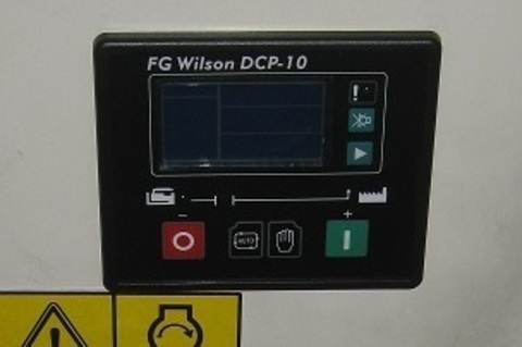
Модель оборудования:
P7.5-4S,
P9.5-4,
P11-6S,
P13.5-6,
P14-6S,
P16-1,
P18-6,
P26-3S,
P40-3S,
P40-4S,
P50-5S,
P55-3,
P165-5,
P200-3,
P200-4,
P300-2,
P300-3,
P330-3,
P344-3
Элемент двигателя:
Генератор и электрика
Бренд:
FG Wilson
Изготовитель:
FG Wilson
Наличие на складах:
| Москва | Краснодар | Екатеринбург | Самара | Новосибирск | Склад №35 (3-5 раб. дней) |
| 38 | 1 | 0 | 0 | 0 | 0 |
Запчасти
и сервис
Гарантия
Контроллер панели управления DCP10 / CONTROLLER DCP10 АРТ: 10000-53990
Если у вас есть вопросы
по этому оборудованию,
вы можете задать их нам: