

Фетальные мониторы Sonicaid Team обеспечивают точное и надежное мониторирование на протяжении дородового периода и во время родов. Фетальный монитор состоит из основной части, которая собирает мониторинговую информацию, и печатного блока.

Модели основного блока Sonicaid Team
Модель Team
Простое наблюдение за сердечным ритмом плода при помощи ультразвукового датчика, и за маточной активностью, используя внешний токовый датчик.
Модель Team Duo
Применяется также, как модель Team, но со вторым ультразвуковым датчиком для мониторирования сердцебиений близнецов.
Модель Team IP
Применяется как для мониторинга сердечного ритма близнецов
при помощи двух ультразвуковых датчиков, или инвазивно с помощью фетального
подкожного головного ЭКГ-электрода и ультразвукового датчика.
Маточная активность может быть измерена или при помощи внешнего токового датчика или при помощи внутриматочного катетерного датчика давления. Эта модель может также измерять частоту сердечных сокращений матери.
Модель Team DM
Для использования в амбулаторных условиях или на дому, располагает теми же возможностями, что и Team, но еще включает модем для передачи сохраненных данных КТГ.
Модели принтеров Sonicaid Team
Стандартный
Термопринтер для продолжительной записи КТГ.
Team Care
Используется для записи КТГ в предродовом периоде.
IP Trend
Этот принтер используется для записи КТГ в интранатальном периоде (во время родов).
Фетальный монитор Sonicaid Team основной блок
Передняя панель
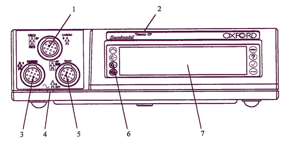
- CARDIO вход, голубой разъем: 2 МГц ультразвуковой датчик, ИЛИ MECG вход: отведение ЭКГ матери (опционно), ИЛИ FECG вход для ножной пластинки фетально ЭКГ-электрода, измеряющего ЭКГ плода.
- Обозначение модели: Team, Team Duo, Team DM или Team IP.
- CARDIO вход, желтый разъем: 1,5 МГц ультразвуковой датчик.
- Индикаторная лампочка включения.
- EXT вход, розовый разъем: внешний датчик маточных сокращений (Toco), ИЛИ INT вход: предварительно откалиброванный катетерный датчик, измеряющий внутриматочное давление (ВМД) (Intrauterine Pressure, IUP).
- Клавиатура, содержащая восемь контрольных кнопок.
- Дисплейная панель.
Задняя панель
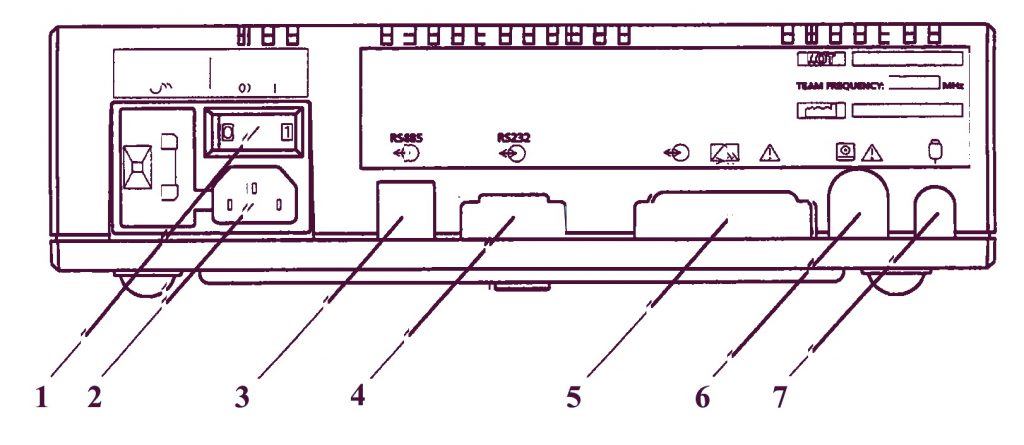
- Основной включатель/выключатель переменного тока: О = выключено, I = включено. Когда Вы включаете прибор, индикатор включения на передней панели загорается зеленым светом.
- Входной разъем для основной подачи переменного тока.
- RS485-разъем подсоединяется к Axis (напряжение пробоя 1,5 кВ постоянного тока). Сменный соединительный кабель (PCC-тип).
- RS232-разъем подсоединяется к PC, работающему с Sonicaid Системой 8000 или 8002 (напряжение пробоя 500В постоянного тока). 9-ти пиновый разъем D-типа («папа»).
- Модемное соединение для дистанционного мониторирования. 25-ти пиновый разъем D-типа. Подсоединять только модемы, которые отвечают требованиям EN60950.
- Разъем для принтера модели Team 8-ми пиновый DIN-типа.
- Гнездо для подсоединения маркера движений плода. ¼”-разъемное стерео-гнездо.
Печатный блок модели Team
Передняя панель
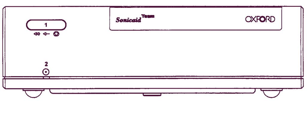
- Основная контрольная кнопка принтера. Нажмите один раз для включения/выключения. Нажмите и держите в нажатом состоянии для быстрой промотки.
- Индикатор включения принтера.
Задняя панель
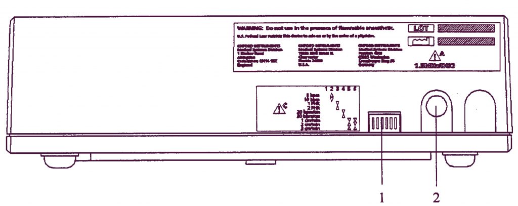
- Переключатели установок принтера.
- Разъем для основного блока (7-ми пиновый DIN-тип). Подключается к разъему принтера на основном блоке модели Team.
Сборка основного блока Team с печатным блоком Team
Основной блок Team поставляется уже в собранном виде вместе с печатным блоком Team.
Разборка
- Нажать спусковую кнопку, находящуюся слева внизу от печатного валика.
- Потянуть валик влево и вверх и снять крышку принтера.
- Вынуть пачку бумаги.
- Используя отвертку, отвинтить центральный фиксирующий болт (необходимо совершить примерно 4 оборота)
- Снять принтерный блок и основного.
- Положить обратно пачку бумаги и печатный валик.
Обратная сборка
- Удалить середину закрывающей пробки (если имеется) сверху на панели основного блока Team.
- Расположить принтерный блок сверху основного блока. Ножки принтера при этом должны попасть в углубление на крышке основного блока.
- Снять печатный валик и поднять пачку бумаги для доступа к головке шурупа снизу.
- Используя отвертку, нажать и тщательно прикрутить шуруп приблизительно на 4 оборота.
- Положить обратно пачку бумаги и печатный валик.
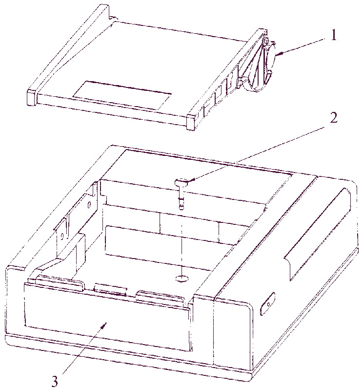
- Показан удаленный печатный валик
- Центральный фиксирующий болт
- Спусковая кнопка
Датчики и кабели Sonicaid Team
Ультразвуковой датчик
Применяется для неинвазивного мониторирования сердечной деятельности плода.
Существует два вида датчиков:
- Основной, желтый, 1,5 МГц.
- Вспомогательный, синий, 2,0 МГц.
Двухмегагерцовый датчик используется только в основных моделях Team Duo или Team IP.
Внешний Токо-датчик

Датчик, обозначенный розовым цветом, может применяться со всеми моделями основных блоков Team.
Ножная пластинка фетального ЭКГ-электрода
Прикрепленный к бедру пациентки, он используется для внутреннего соединения между фетальным монитором и подкожным головным ЭКГ-электродом плода. Он выкрашен синим, и может использоваться только в комплексе с основным блоком Team IP.
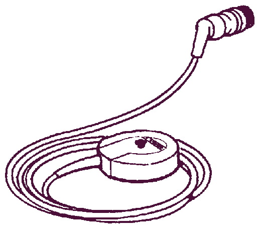
Маркер движений плода
Пациентка использует этот ручной провод с кнопкой для записи движений плода. Он может применяться с любой моделью фетального монитора Team.

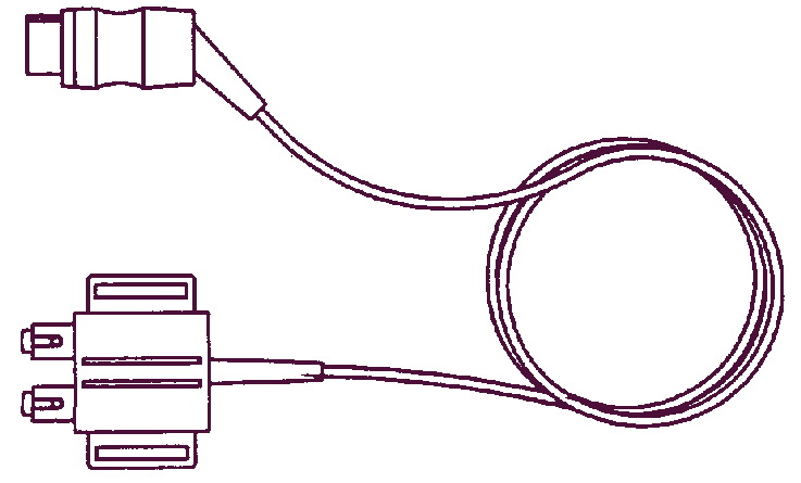
Соединительный провод для внутриматочного датчика давления
Используется для взаимосвязи между монитором Team и внутриматочным датчиком давления. Он окрашен в розовый цвет и может применяться только с моделью Team IP. Этот провод не входит в основной комплект поставки, но может быть предоставлен в качестве дополнительного оборудования.
Кабель для записи ЭКГ матери
Применяется для мониторирования сердечного ритма матери, для проверки, что записываемый сердечный ритм принадлежит плоду, а не матери. Он окрашен в синий цвет, и может использоваться только с моделью Team IP. Этот провод не входит в основной комплект поставки, но может быть предоставлен в качестве дополнительного оборудования.
Место для хранения датчиков
В то время, когда они не используются, ультразвуковой и токовый датчики могут находиться прикрепленными фиксатором на специальной вешалке на задней стенке с правой стороны основного блока Team.
Дисплей Sonicaid Team
Дисплейная панель основного блока имеет два режима для вывода мониторинговой информации: буквенно-цифровой и демонстрация КТГ.
Буквенно-цифровой режим
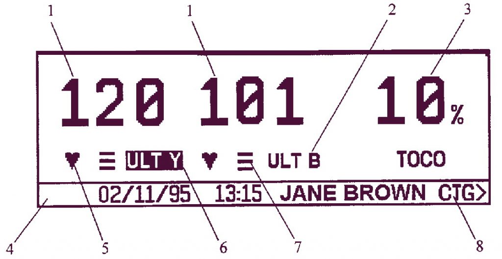
- Частота сердечных сокращений, в ударах в минуту.
- Канальный режим, показывает источник мониторинговой информации.
- Измерения силы сокращений матки.
- Строка сообщений: включает дату, время проведения исследования и имя пациентки (если введено). Также используется для вывода интерактивной информации.
- Мигающая лампочка, показывающая ритм сокращений сердца.
- Активный аудио канал: выделяется подсветкой в канальном режиме.
- Индикатор качества сигнала.
- CTG > : нажмите эту клавишу, чтобы перейти в режим КГТ.
Режим КТГ
- Частота сердечных сокращений (удары в минуту): показывает разброс текущей записываемой частоты.
- Мигающая индикаторная лампочка сердечного ритма.
- Режим записи (канал): показывает, по какому каналу производится запись.
- Строка сообщений, используемая для вывода интерактивной информации.
- Кривая изменения частоты сердечных сокращений: Выводится активный аудио канал (или канал 1, желтый, если не выделен аудио). Если производится мониторирование ритмов сердца близнецов, на дисплей одновременно может быть выведен только один канал.
- Кривая сократительной активности матки, сжата.
- CTG > : это указатель в меню имеет изменяемое название и назначение. См. прокрутку КТГ ниже.
Пульт управления фетальным монитором Sonicaid Team
- Обнуление Токо: сброс значений внешнего Токо-датчика или внутриматочного датчика давления.
- Увеличение громкости.
- Уменьшение громкости.
- Выбор канала.
- Вход в основное меню.
- Вывод справочной информации.
- Маркер клинического результата (события).
- Клавиша Ввод (Enter): для подтверждения ввода или переключения дисплейных режимов.
Процедуры записи Sonicaid Team
Положение датчиков
- Пропальпируйте живот беременной женщины для определения положения плода.
- Расположите токовый датчик (розовый) в центре, посередине между дном матки и пупком. Не используйте гель. Закрепите с помощью ремня с пряжкой.
- Сбросьте значения Токо. Убедитесь, что матка расслаблена (находится в нормальном тонусе), затем нажмите кнопку обнуления Токо. На дисплее высвечивается десятипроцентный исходный уровень.
- Возьмите ультразвуковой датчик (желтый). Положите его на живот так, чтобы можно было слышать четкие звуки сердечной деятельности. Закрепите при помощи ремня с пряжкой.
- Убедитесь, что Вы слышите именно сердце плода, отдельно от сердцебиения матери, что можно проверить, прощупав пульс на запястье беременной женщины. Оптимальное качество сигнала для сердцебиения плода обозначается тремя полосами на экране, с миганием иконки сердца при каждом ударе.
- Отрегулируйте громкость, используя кнопки увеличения и уменьшения громкости.
- Подсоедините маркер движений плода к гнезду на задней панели. Покажите пациентке, как им пользоваться.
Использование печатающего устройства
- Чтобы включить принтер нажмите кнопку на передней панели принтера.
- Для быстрой промотки бумаги нажмите и держите нажатой кнопку принтера.
- Для остановки записи еще раз нажмите кнопку принтера.
Использование второго ультразвукового датчика для мониторирования близнецов
- Подсоедините второй ультразвуковой датчик (синий) к
прибору. Дисплей переключится в режим для двойного изображения. - Положите оба ультразвуковых датчика на живот пациентки
в оптимальной позиции. - Используйте голубой ультразвуковой датчик для
мониторирования первого, предлежащего близнеца. - Убедитесь, что каждый сердечный ритм исходит от разных
плодов. Если есть сомнения, посоветуйтесь с ассистентом. Закрепите датчики при
помощи ремней с пряжками. - Для того чтобы выбрать Аудио, нажмите левую кнопку на
пульте управления. Активный аудио канал высвечивается на дисплее.
Использование фетального подкожного головного ЭКГ-электрода
- Подключите ножную пластинку электрода (синяя) к прибору.
- Нанесите электродный гель на основание пластинки, затем прикрепите пластинку к бедру пациентки. Закрепите ремнем.
- Подсоедините электрод к плоду как сказано в инструкции по использованию электрода.
- Подключите провод, идущий от электрода к пластинке. Убедитесь, что сохраняется хорошее качество сигнала.
Печатный блок Sonicaid Team
Существует три типа печатных блоков для модели Team:
| Стандартный | Термопринтер для продолжительной записи мониторируемой КТГ на бумаге. |
| Team Care | Включает анализ КТГ для использования в предродовом периоде. Анализу подвергаются параметры фетального сердечного ритма, проводится тестовое сравнение с нормальными критериями, и обозначаются любые отклонения. |
| Team IP | Включает анализ КТГ для использования во время родов. Анализируется сердечный ритм на регулярность интервалов, что позволяет улучшить идентификацию подозрительных изменений в работе сердца. |
Описанные методы, относящиеся к записи КТГ, загрузка бумаги и пользование опциями принтера применимы ко всем трем типам печатных блоков. См. раздел по Использованию печатного блока Team Care и Использованию печатного блока Team IP для получения более подробной специфической информации касательно каждого принтера в отдельности.
Бумага для Печатного блока Sonicaid Team
Печатающее устройство использует плоские блоки термобумаги (номер партии 8400-8003). Используйте только специальную бумагу (Oxford Instruments Sonicaid). Использование несанкционированной бумаги может привести к низкокачественным результатам печати или поломке принтера, и отменяет гарантийные обязательства фирмы.
Описание кривой КТГ Sonicaid Team
Шапка КТГ
Когда включается принтер, перед началом записи данных КТГ и градуировкой печатается шапка. Она включает имя пользователя, дату и время проведения исследования и информацию о пациентке (если таковая имеется).
Градуировка КТГ
Градуировка печатается одновременно с данными КТГ, с шагом 5 или 10 уд/мин. Можно установить переключатель 2 на печатном блоке в положение «вверх» для шага 5 уд/мин, и в положение «вниз» для шага 10 уд/мин.
Масштаб при записи сердечного ритма плода
Установите переключатель 4 на печатном блоке в положение «вниз» для 20 ударов в мин/см (разброс 50-210 уд/мин), или в положение «вверх» для 30 ударов в мин/см (разброс 30-240 уд/мин).
Сердечные ритмы близнецов
Установите переключатель 3 в положение «вниз» для вывода на
печать кривых частоты сердечных сокращений близнецов, наложенных на развернутую
шкалу сердечного ритма плода, или в положение «вверх» для печати параллельных
или раздельных шкал частоты сердечных сокращений плода.
При печати в параллельном режиме, первый канал (ULT-Y) печатается на верхней шкале, второй канал (ULT-B или FECG или MECG) ниже. Разброс возможных значений СРП (сердечного ритма плода) зависит от выбранного масштаба:
| 20 ударов в мин/см | 30 ударов в мин/см |
| 100-180 уд/мин | 60-180 уд/мин |
При печати в наложенном режиме, первый канал (ULT-Y) печатается в виде сплошной линии, а второй канал (ULT-B или FECG или MECG) печатается в виде пунктирной линии.
Шкалы для записи сокращений матки
Когда используется внешний Токовый датчик, шкала сокращений
выражается в относительных единицах (0-100%).
Когда используется внутриматочный датчик давления, шкала: или 0-100 ммHg, или 0-15 кПа, в зависимости от того, какой тип измерения выбран.
Комментарий КТГ
Печатающий блок автоматически выводит комментарий к кривой
КТГ со следующей информацией:
- Масштаб частоты сердечных сокращений
- Шкала сокращений матки
- Режим мониторирования
- Время и дата проведения исследования
- Скорость прохода бумаги
- Процент потери сигнала
Комментарий печатается при включении принтера и затем с 10-и минутными интервалами (при скорости 1 см/мин) или с 5-и минутными интервалами (при скорости 2 или 3 см/мин). Каждый час вначале разделяется на 5-и или 10-и минутные промежутки, таким образом, следующий комментарий может не быть напечатан в течение 19 минут.
Загрузка бумаги в принтер Sonicaid Team

- Нажмите кнопку, находящуюся под левым краем печатного валика.
- Поднимите валик влево и снимите крышку принтера.
- Положите пачку бумаги в отделение внизу. (Верхняя сторона новой пачки бумаги помечена символом «LOAD PACK», и стрелкой, указывающей вправо. Для частично использованной пачки, совместите синие метки на пачке с синими метками в отделении.)
- Натяните два листа вправо, как показано на рисунке.
- Затем загните их обратно влево, через верх валика, так чтобы он прижался к нижнему правому углу.
- При необходимости отрегулируйте положение бумаги и нажмите вниз на левую сторону печатного валика для того, чтобы защелкнуть его.
Если после некоторого времени использования качество печати плохое, проверьте, что валик плотно защелкнут. Если это не помогает, прочистите головку принтера как объяснено в разделе Техническое Обслуживание.
Изменение языка Sonicaid Team
Программные меню Team существуют на разных языках. Для того
чтобы выбрать необходимый язык:
- В меню [VERSION] выберите [RECONFIGURE] (Изменение конфигурации).
- Team выдаст сообщение: EXIT, THEN TURN UNIT OFF TO RECONFIGURE.(ВЫХОД, ЗАТЕМ ВЫКЛЮЧИТЬ ПРИБОР ДЛЯ ИЗМЕНЕНИЯ КОНФИГУРАЦИИ)
- Выберите [EXIT].
- Выключите прибор, а затем снова включите.
- Программа покажет все доступные языки. Выберите необходимый язык. Используя клавишу [ >>>] для просмотра всего списка.
Принтер Sonicaid Team IP Trend
Принтер Team IP Trend включает в себя систему анализа КТГ
для использования во время периода родов. Анализ, который предусматривает
измерение параметров сердечного ритма плода по регулярным интервалам,
предлагает новый способ описания свойств кривой КТГ как количественных, так и
качественных. Это не предполагает замещения квалифицированной визуальной
интерпретации кривой КТГ.
Применяя данный анализ с продолжительным фетальным мониторированием, Вы можете оценивать устойчивые изменения в характере сердечного ритма плода. Не предусмотрено норм для интерпретации или ограничений в нормальном состоянии. Кроме того, клиницисты могут использовать количественные значения для идентификации и измерения относительных изменений в параметрах сердечного ритма на протяжении всего периода времени.
Числовое описание кривой КТГ позволяет проводить непосредственное прямое сравнение между различными кривыми. Это также предусматривает обучающую поддержку для интерпретации результатов и быстрый доступ к данным для клинических исследовательских проектов.
Sonicaid Team технические характеристики
Физические
Ширина 275 ´ Высота 83 ´ Глубина 275мм Примерно 3 кг Ширина 275 ´ Высота 83 ´ Глубина 236мм Примерно 2,5 кг
Рекомендуемые условия для работы и хранения
| Рабочая температура | 10 – 35°С (50 – 96°F) |
| Температура хранения | -20 – 60°С (-4 – 140°F) |
| Давление в месте хранения | 68 – 106 кПа (680 – 1060 мБр) |
| Влажность в месте хранения | 10 – 100% относительной влажности |
Напряжение питающего переменного тока и маркировка предохранителей
| Номинальное напряжение питающего переменного тока | 110В / 120B / 220B / 240B ± 10% 50Гц / 60Гц, максимальная номинальная мощность 30Ватт |
| Маркировка предохранителей | T160мА для номинального входного напряжения 220-240В Т315мА для номинального входного напряжения 110-120В |
Принтер
5’’ диаграммный принтер высокого разрешения с автоматическим комментарием, определением потери сигнала, датой, временем, и скоростью печати. Термическая матричная печать, 1024 элемента. Ширина печати 128мм.
Чистка прибора и стерилизация
Чистка Sonicaid Team
Протрите футляр для инструментов, датчики, маркер событий, ножную пластинку фетального ЭКГ-электрода и внешний кабель датчика, измеряющего внутриматочное давление мягкой тканью, смоченной в мыльном или растворе детергента, для удаления акустического геля, крови, соли и так далее. Насухо вытрите чистой тканью.
Дезинфекционная обработка провода для записи ЭКГ матери
- Протрите
тканью, смоченной в водном растворе хлора (концентрация не боле 1:10) или в 2%
растворе глутаральдегида, как, например Cidex. - Вытрите
провод влажной тряпкой, затем сухой тряпкой.
Дезинфекция, общие положения
Очистите футляр для инструментов, датчики и так далее, как
сказано выше. Затем протрите пропитанной спиртом тканью (70% этанол или
изопропанол).
Стерилизация
Для стерилизации футляра и датчиков используется метод с применением газа Оксида Этилена (при 5,5 бар). НЕ РАЗРЕШАЕТСЯ применять низкотемпературный пар.
Уход за датчиками
Датчики должны храниться в сухом месте предпочтительно при температуре ниже 45°С. После использования и перед помещением на место хранения необходимо удалять остатки геля с поверхности ультразвукового датчика.
Бумага для принтера Sonicaid Team
Использовать только специальную бумагу фирмы Oxford Instruments Sonicaid. Использование неадаптированной бумаги может привести к ухудшению качества печати или поломке принтера, что не будет являться гарантийными условиями.
Техническое обслуживание Sonicaid Team
Процедуры, описанные ниже должны проводиться с интервалом от трех месяцев до года, в зависимости от интенсивности использования и внешних условий.
Проверка и замена предохранителей
- Удалите
отсек с предохранителями, используя для этой цели маленькую отвертку. - Приподнимите
маленькую защелку и удалите щиток с предохранителями для того, чтобы достать
сами предохранители. - Проверьте,
что предохранители питающего переменного тока имеют правильные маркировки:
- Т315мА для 110-120В сетей.
- Т160мА для 220-240В сетей.
Механический осмотр Sonicaid Team
Осмотрите питающий кабель переменного тока, датчики, все остальные принадлежности и соединительные провода для обнаружения незакрепленных или сломанных частей, а также любых других повреждений. Будьте особенно внимательны к гнезду для переменного сетевого тока. Тщательно осмотрите, нет ли где-нибудь щелей, в которые могли бы попасть жидкость или гель. При необходимости почините или замените пришедшие в негодность детали.
Функциональная проверка
- Подсоедините
питание (переменный ток сети), датчики и другие необходимые элементы. - Включите
прибор. - Проверьте,
что аппарат может осуществлять функции, описанные в настоящем руководстве.
Средства самопроверки принтера
Для запуска самопроверки принтера:
- Установите все DIP переключатели на задней панели принтера в положение Включено (вниз).
- Включите принтер Team. Принтер напечатает шкалу из 20 ударов в минуту, при скорости 3 см/мин.
- Проверьте, что подача бумаги осуществляется корректно и что установлена правильная скорость.
- Проверьте качество печати принтера.
- Установите все переключатели обратно в требуемые позиции.
Очистка печатной головки графического принтера
Если качество печати диаграмм снизилось, в первую очередь проверьте правильность установки печатного валика (полностью утоплен вниз). Если ничего не изменилось, произведите чистку головки принтера, как сказано ниже:
- Выньте печатный валик и пачку бумаги.
- Используя непыльную ткань и низкопроцентный спирт, протрите печатающую головку, которая находится ниже пластикового края отделения для бумаги, по всей ширине.
- Положите обратно пачку бумаги и печатный валик.
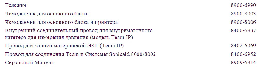
Sonicaid Team аксессуары, расходные материалы и запасные детали
Аксессуары Sonicaid Team
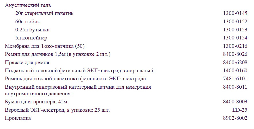
Расходные материалы Sonicaid Team
Запасные детали Sonicaid Team

Скачать инструкцию на фетальный монитор Sonicaid Team
Скачать инструкцию и другую документацию на Sonicaid Team можно здесь.
Руководство пользователя ( user manual ) на русском языке Sonicaid Team скачать.
Регистрационное удостоверение Sonicaid Team скачать.
Так же смотрите УЗИ аппарат LOGIQ S8 GE.
Фетальные мониторы Sonicaid Team обеспечивают точное и надежное мониторирование на протяжении дородового периода и во время родов. Фетальный монитор состоит из основной части, которая собирает мониторинговую информацию, и печатного блока.
Модель Team
Простое наблюдение за сердечным ритмом плода при помощи ультразвукового датчика, и за маточной активностью, используя внешний токовый датчик.
Модель Team Duo
Применяется также, как модель Team, но со вторым ультразвуковым датчиком для мониторирования сердцебиений близнецов.
Модель Team IP
Применяется как для мониторинга сердечного ритма близнецов
при помощи двух ультразвуковых датчиков, или инвазивно с помощью фетального
подкожного головного ЭКГ-электрода и ультразвукового датчика.
Маточная активность может быть измерена или при помощи внешнего токового датчика или при помощи внутриматочного катетерного датчика давления. Эта модель может также измерять частоту сердечных сокращений матери.
Модель Team DM
Для использования в амбулаторных условиях или на дому, располагает теми же возможностями, что и Team, но еще включает модем для передачи сохраненных данных КТГ.
Модели принтеров Sonicaid Team
Стандартный
Термопринтер для продолжительной записи КТГ.
Team Care
Используется для записи КТГ в предродовом периоде.
IP Trend
Этот принтер используется для записи КТГ в интранатальном периоде (во время родов).
Фетальный монитор Sonicaid Team основной блок
Передняя панель
- CARDIO вход, голубой разъем: 2 МГц ультразвуковой датчик, ИЛИ MECG вход: отведение ЭКГ матери (опционно), ИЛИ FECG вход для ножной пластинки фетально ЭКГ-электрода, измеряющего ЭКГ плода.
- Обозначение модели: Team, Team Duo, Team DM или Team IP.
- CARDIO вход, желтый разъем: 1,5 МГц ультразвуковой датчик.
- Индикаторная лампочка включения.
- EXT вход, розовый разъем: внешний датчик маточных сокращений (Toco), ИЛИ INT вход: предварительно откалиброванный катетерный датчик, измеряющий внутриматочное давление (ВМД) (Intrauterine Pressure, IUP).
- Клавиатура, содержащая восемь контрольных кнопок.
- Дисплейная панель.
Задняя панель
- Основной включатель/выключатель переменного тока: О = выключено, I = включено. Когда Вы включаете прибор, индикатор включения на передней панели загорается зеленым светом.
- Входной разъем для основной подачи переменного тока.
- RS485-разъем подсоединяется к Axis (напряжение пробоя 1,5 кВ постоянного тока). Сменный соединительный кабель (PCC-тип).
- RS232-разъем подсоединяется к PC, работающему с Sonicaid Системой 8000 или 8002 (напряжение пробоя 500В постоянного тока). 9-ти пиновый разъем D-типа («папа»).
- Модемное соединение для дистанционного мониторирования. 25-ти пиновый разъем D-типа. Подсоединять только модемы, которые отвечают требованиям EN60950.
- Разъем для принтера модели Team 8-ми пиновый DIN-типа.
- Гнездо для подсоединения маркера движений плода. ¼”-разъемное стерео-гнездо.
Печатный блок модели Team
Передняя панель
- Основная контрольная кнопка принтера. Нажмите один раз для включения/выключения. Нажмите и держите в нажатом состоянии для быстрой промотки.
- Индикатор включения принтера.
Задняя панель
- Переключатели установок принтера.
- Разъем для основного блока (7-ми пиновый DIN-тип). Подключается к разъему принтера на основном блоке модели Team.
Сборка основного блока Team с печатным блоком Team
Основной блок Team поставляется уже в собранном виде вместе с печатным блоком Team.
Разборка
- Нажать спусковую кнопку, находящуюся слева внизу от печатного валика.
- Потянуть валик влево и вверх и снять крышку принтера.
- Вынуть пачку бумаги.
- Используя отвертку, отвинтить центральный фиксирующий болт (необходимо совершить примерно 4 оборота)
- Снять принтерный блок и основного.
- Положить обратно пачку бумаги и печатный валик.
Обратная сборка
- Удалить середину закрывающей пробки (если имеется) сверху на панели основного блока Team.
- Расположить принтерный блок сверху основного блока. Ножки принтера при этом должны попасть в углубление на крышке основного блока.
- Снять печатный валик и поднять пачку бумаги для доступа к головке шурупа снизу.
- Используя отвертку, нажать и тщательно прикрутить шуруп приблизительно на 4 оборота.
- Положить обратно пачку бумаги и печатный валик.
- Показан удаленный печатный валик
- Центральный фиксирующий болт
- Спусковая кнопка
Датчики и кабели Sonicaid Team
Ультразвуковой датчик
Применяется для неинвазивного мониторирования сердечной деятельности плода.
Существует два вида датчиков:
- Основной, желтый, 1,5 МГц.
- Вспомогательный, синий, 2,0 МГц.
Двухмегагерцовый датчик используется только в основных моделях Team Duo или Team IP.
Внешний Токо-датчик
Датчик, обозначенный розовым цветом, может применяться со всеми моделями основных блоков Team.
Ножная пластинка фетального ЭКГ-электрода
Прикрепленный к бедру пациентки, он используется для внутреннего соединения между фетальным монитором и подкожным головным ЭКГ-электродом плода. Он выкрашен синим, и может использоваться только в комплексе с основным блоком Team IP.
Маркер движений плода
Пациентка использует этот ручной провод с кнопкой для записи движений плода. Он может применяться с любой моделью фетального монитора Team.
Соединительный провод для внутриматочного датчика давления
Используется для взаимосвязи между монитором Team и внутриматочным датчиком давления. Он окрашен в розовый цвет и может применяться только с моделью Team IP. Этот провод не входит в основной комплект поставки, но может быть предоставлен в качестве дополнительного оборудования.
Кабель для записи ЭКГ матери
Применяется для мониторирования сердечного ритма матери, для проверки, что записываемый сердечный ритм принадлежит плоду, а не матери. Он окрашен в синий цвет, и может использоваться только с моделью Team IP. Этот провод не входит в основной комплект поставки, но может быть предоставлен в качестве дополнительного оборудования.
Место для хранения датчиков
В то время, когда они не используются, ультразвуковой и токовый датчики могут находиться прикрепленными фиксатором на специальной вешалке на задней стенке с правой стороны основного блока Team.
Дисплей Sonicaid Team
Дисплейная панель основного блока имеет два режима для вывода мониторинговой информации: буквенно-цифровой и демонстрация КТГ.
Буквенно-цифровой режим
- Частота сердечных сокращений, в ударах в минуту.
- Канальный режим, показывает источник мониторинговой информации.
- Измерения силы сокращений матки.
- Строка сообщений: включает дату, время проведения исследования и имя пациентки (если введено). Также используется для вывода интерактивной информации.
- Мигающая лампочка, показывающая ритм сокращений сердца.
- Активный аудио канал: выделяется подсветкой в канальном режиме.
- Индикатор качества сигнала.
- CTG > : нажмите эту клавишу, чтобы перейти в режим КГТ.
Режим КТГ
- Частота сердечных сокращений (удары в минуту): показывает разброс текущей записываемой частоты.
- Мигающая индикаторная лампочка сердечного ритма.
- Режим записи (канал): показывает, по какому каналу производится запись.
- Строка сообщений, используемая для вывода интерактивной информации.
- Кривая изменения частоты сердечных сокращений: Выводится активный аудио канал (или канал 1, желтый, если не выделен аудио). Если производится мониторирование ритмов сердца близнецов, на дисплей одновременно может быть выведен только один канал.
- Кривая сократительной активности матки, сжата.
- CTG > : это указатель в меню имеет изменяемое название и назначение. См. прокрутку КТГ ниже.
Пульт управления фетальным монитором Sonicaid Team
- Обнуление Токо: сброс значений внешнего Токо-датчика или внутриматочного датчика давления.
- Увеличение громкости.
- Уменьшение громкости.
- Выбор канала.
- Вход в основное меню.
- Вывод справочной информации.
- Маркер клинического результата (события).
- Клавиша Ввод (Enter): для подтверждения ввода или переключения дисплейных режимов.
Процедуры записи Sonicaid Team
Положение датчиков
- Пропальпируйте живот беременной женщины для определения положения плода.
- Расположите токовый датчик (розовый) в центре, посередине между дном матки и пупком. Не используйте гель. Закрепите с помощью ремня с пряжкой.
- Сбросьте значения Токо. Убедитесь, что матка расслаблена (находится в нормальном тонусе), затем нажмите кнопку обнуления Токо. На дисплее высвечивается десятипроцентный исходный уровень.
- Возьмите ультразвуковой датчик (желтый). Положите его на живот так, чтобы можно было слышать четкие звуки сердечной деятельности. Закрепите при помощи ремня с пряжкой.
- Убедитесь, что Вы слышите именно сердце плода, отдельно от сердцебиения матери, что можно проверить, прощупав пульс на запястье беременной женщины. Оптимальное качество сигнала для сердцебиения плода обозначается тремя полосами на экране, с миганием иконки сердца при каждом ударе.
- Отрегулируйте громкость, используя кнопки увеличения и уменьшения громкости.
- Подсоедините маркер движений плода к гнезду на задней панели. Покажите пациентке, как им пользоваться.
Использование печатающего устройства
- Чтобы включить принтер нажмите кнопку на передней панели принтера.
- Для быстрой промотки бумаги нажмите и держите нажатой кнопку принтера.
- Для остановки записи еще раз нажмите кнопку принтера.
Использование второго ультразвукового датчика для мониторирования близнецов
- Подсоедините второй ультразвуковой датчик (синий) к
прибору. Дисплей переключится в режим для двойного изображения. - Положите оба ультразвуковых датчика на живот пациентки
в оптимальной позиции. - Используйте голубой ультразвуковой датчик для
мониторирования первого, предлежащего близнеца. - Убедитесь, что каждый сердечный ритм исходит от разных
плодов. Если есть сомнения, посоветуйтесь с ассистентом. Закрепите датчики при
помощи ремней с пряжками. - Для того чтобы выбрать Аудио, нажмите левую кнопку на
пульте управления. Активный аудио канал высвечивается на дисплее.
Использование фетального подкожного головного ЭКГ-электрода
- Подключите ножную пластинку электрода (синяя) к прибору.
- Нанесите электродный гель на основание пластинки, затем прикрепите пластинку к бедру пациентки. Закрепите ремнем.
- Подсоедините электрод к плоду как сказано в инструкции по использованию электрода.
- Подключите провод, идущий от электрода к пластинке. Убедитесь, что сохраняется хорошее качество сигнала.
Печатный блок Sonicaid Team
Существует три типа печатных блоков для модели Team:
| Стандартный | Термопринтер для продолжительной записи мониторируемой КТГ на бумаге. |
| Team Care | Включает анализ КТГ для использования в предродовом периоде. Анализу подвергаются параметры фетального сердечного ритма, проводится тестовое сравнение с нормальными критериями, и обозначаются любые отклонения. |
| Team IP | Включает анализ КТГ для использования во время родов. Анализируется сердечный ритм на регулярность интервалов, что позволяет улучшить идентификацию подозрительных изменений в работе сердца. |
Описанные методы, относящиеся к записи КТГ, загрузка бумаги и пользование опциями принтера применимы ко всем трем типам печатных блоков. См. раздел по Использованию печатного блока Team Care и Использованию печатного блока Team IP для получения более подробной специфической информации касательно каждого принтера в отдельности.
Бумага для Печатного блока Sonicaid Team
Печатающее устройство использует плоские блоки термобумаги (номер партии 8400-8003). Используйте только специальную бумагу (Oxford Instruments Sonicaid). Использование несанкционированной бумаги может привести к низкокачественным результатам печати или поломке принтера, и отменяет гарантийные обязательства фирмы.
Описание кривой КТГ Sonicaid Team
Шапка КТГ
Когда включается принтер, перед началом записи данных КТГ и градуировкой печатается шапка. Она включает имя пользователя, дату и время проведения исследования и информацию о пациентке (если таковая имеется).
Градуировка КТГ
Градуировка печатается одновременно с данными КТГ, с шагом 5 или 10 уд/мин. Можно установить переключатель 2 на печатном блоке в положение «вверх» для шага 5 уд/мин, и в положение «вниз» для шага 10 уд/мин.
Масштаб при записи сердечного ритма плода
Установите переключатель 4 на печатном блоке в положение «вниз» для 20 ударов в мин/см (разброс 50-210 уд/мин), или в положение «вверх» для 30 ударов в мин/см (разброс 30-240 уд/мин).
Сердечные ритмы близнецов
Установите переключатель 3 в положение «вниз» для вывода на
печать кривых частоты сердечных сокращений близнецов, наложенных на развернутую
шкалу сердечного ритма плода, или в положение «вверх» для печати параллельных
или раздельных шкал частоты сердечных сокращений плода.
При печати в параллельном режиме, первый канал (ULT-Y) печатается на верхней шкале, второй канал (ULT-B или FECG или MECG) ниже. Разброс возможных значений СРП (сердечного ритма плода) зависит от выбранного масштаба:
| 20 ударов в мин/см | 30 ударов в мин/см |
| 100-180 уд/мин | 60-180 уд/мин |
При печати в наложенном режиме, первый канал (ULT-Y) печатается в виде сплошной линии, а второй канал (ULT-B или FECG или MECG) печатается в виде пунктирной линии.
Шкалы для записи сокращений матки
Когда используется внешний Токовый датчик, шкала сокращений
выражается в относительных единицах (0-100%).
Когда используется внутриматочный датчик давления, шкала: или 0-100 ммHg, или 0-15 кПа, в зависимости от того, какой тип измерения выбран.
Комментарий КТГ
Печатающий блок автоматически выводит комментарий к кривой
КТГ со следующей информацией:
- Масштаб частоты сердечных сокращений
- Шкала сокращений матки
- Режим мониторирования
- Время и дата проведения исследования
- Скорость прохода бумаги
- Процент потери сигнала
Комментарий печатается при включении принтера и затем с 10-и минутными интервалами (при скорости 1 см/мин) или с 5-и минутными интервалами (при скорости 2 или 3 см/мин). Каждый час вначале разделяется на 5-и или 10-и минутные промежутки, таким образом, следующий комментарий может не быть напечатан в течение 19 минут.
Загрузка бумаги в принтер Sonicaid Team
- Нажмите кнопку, находящуюся под левым краем печатного валика.
- Поднимите валик влево и снимите крышку принтера.
- Положите пачку бумаги в отделение внизу. (Верхняя сторона новой пачки бумаги помечена символом «LOAD PACK», и стрелкой, указывающей вправо. Для частично использованной пачки, совместите синие метки на пачке с синими метками в отделении.)
- Натяните два листа вправо, как показано на рисунке.
- Затем загните их обратно влево, через верх валика, так чтобы он прижался к нижнему правому углу.
- При необходимости отрегулируйте положение бумаги и нажмите вниз на левую сторону печатного валика для того, чтобы защелкнуть его.
Если после некоторого времени использования качество печати плохое, проверьте, что валик плотно защелкнут. Если это не помогает, прочистите головку принтера как объяснено в разделе Техническое Обслуживание.
Изменение языка Sonicaid Team
Программные меню Team существуют на разных языках. Для того
чтобы выбрать необходимый язык:
- В меню [VERSION] выберите [RECONFIGURE] (Изменение конфигурации).
- Team выдаст сообщение: EXIT, THEN TURN UNIT OFF TO RECONFIGURE.(ВЫХОД, ЗАТЕМ ВЫКЛЮЧИТЬ ПРИБОР ДЛЯ ИЗМЕНЕНИЯ КОНФИГУРАЦИИ)
- Выберите [EXIT].
- Выключите прибор, а затем снова включите.
- Программа покажет все доступные языки. Выберите необходимый язык. Используя клавишу [ >>>] для просмотра всего списка.
Принтер Sonicaid Team IP Trend
Принтер Team IP Trend включает в себя систему анализа КТГ
для использования во время периода родов. Анализ, который предусматривает
измерение параметров сердечного ритма плода по регулярным интервалам,
предлагает новый способ описания свойств кривой КТГ как количественных, так и
качественных. Это не предполагает замещения квалифицированной визуальной
интерпретации кривой КТГ.
Применяя данный анализ с продолжительным фетальным мониторированием, Вы можете оценивать устойчивые изменения в характере сердечного ритма плода. Не предусмотрено норм для интерпретации или ограничений в нормальном состоянии. Кроме того, клиницисты могут использовать количественные значения для идентификации и измерения относительных изменений в параметрах сердечного ритма на протяжении всего периода времени.
Числовое описание кривой КТГ позволяет проводить непосредственное прямое сравнение между различными кривыми. Это также предусматривает обучающую поддержку для интерпретации результатов и быстрый доступ к данным для клинических исследовательских проектов.
Sonicaid Team технические характеристики
Физические
Ширина 275 ´ Высота 83 ´ Глубина 275мм Примерно 3 кг Ширина 275 ´ Высота 83 ´ Глубина 236мм Примерно 2,5 кг
Рекомендуемые условия для работы и хранения
| Рабочая температура | 10 – 35°С (50 – 96°F) |
| Температура хранения | -20 – 60°С (-4 – 140°F) |
| Давление в месте хранения | 68 – 106 кПа (680 – 1060 мБр) |
| Влажность в месте хранения | 10 – 100% относительной влажности |
Напряжение питающего переменного тока и маркировка предохранителей
| Номинальное напряжение питающего переменного тока | 110В / 120B / 220B / 240B ± 10% 50Гц / 60Гц, максимальная номинальная мощность 30Ватт |
| Маркировка предохранителей | T160мА для номинального входного напряжения 220-240В Т315мА для номинального входного напряжения 110-120В |
Принтер
5’’ диаграммный принтер высокого разрешения с автоматическим комментарием, определением потери сигнала, датой, временем, и скоростью печати. Термическая матричная печать, 1024 элемента. Ширина печати 128мм.
Чистка прибора и стерилизация
Чистка Sonicaid Team
Протрите футляр для инструментов, датчики, маркер событий, ножную пластинку фетального ЭКГ-электрода и внешний кабель датчика, измеряющего внутриматочное давление мягкой тканью, смоченной в мыльном или растворе детергента, для удаления акустического геля, крови, соли и так далее. Насухо вытрите чистой тканью.
Дезинфекционная обработка провода для записи ЭКГ матери
- Протрите
тканью, смоченной в водном растворе хлора (концентрация не боле 1:10) или в 2%
растворе глутаральдегида, как, например Cidex. - Вытрите
провод влажной тряпкой, затем сухой тряпкой.
Дезинфекция, общие положения
Очистите футляр для инструментов, датчики и так далее, как
сказано выше. Затем протрите пропитанной спиртом тканью (70% этанол или
изопропанол).
Стерилизация
Для стерилизации футляра и датчиков используется метод с применением газа Оксида Этилена (при 5,5 бар). НЕ РАЗРЕШАЕТСЯ применять низкотемпературный пар.
Уход за датчиками
Датчики должны храниться в сухом месте предпочтительно при температуре ниже 45°С. После использования и перед помещением на место хранения необходимо удалять остатки геля с поверхности ультразвукового датчика.
Бумага для принтера Sonicaid Team
Использовать только специальную бумагу фирмы Oxford Instruments Sonicaid. Использование неадаптированной бумаги может привести к ухудшению качества печати или поломке принтера, что не будет являться гарантийными условиями.
Техническое обслуживание Sonicaid Team
Процедуры, описанные ниже должны проводиться с интервалом от трех месяцев до года, в зависимости от интенсивности использования и внешних условий.
Проверка и замена предохранителей
- Удалите
отсек с предохранителями, используя для этой цели маленькую отвертку. - Приподнимите
маленькую защелку и удалите щиток с предохранителями для того, чтобы достать
сами предохранители. - Проверьте,
что предохранители питающего переменного тока имеют правильные маркировки:
- Т315мА для 110-120В сетей.
- Т160мА для 220-240В сетей.
Механический осмотр Sonicaid Team
Осмотрите питающий кабель переменного тока, датчики, все остальные принадлежности и соединительные провода для обнаружения незакрепленных или сломанных частей, а также любых других повреждений. Будьте особенно внимательны к гнезду для переменного сетевого тока. Тщательно осмотрите, нет ли где-нибудь щелей, в которые могли бы попасть жидкость или гель. При необходимости почините или замените пришедшие в негодность детали.
Функциональная проверка
- Подсоедините
питание (переменный ток сети), датчики и другие необходимые элементы. - Включите
прибор. - Проверьте,
что аппарат может осуществлять функции, описанные в настоящем руководстве.
Средства самопроверки принтера
Для запуска самопроверки принтера:
- Установите все DIP переключатели на задней панели принтера в положение Включено (вниз).
- Включите принтер Team. Принтер напечатает шкалу из 20 ударов в минуту, при скорости 3 см/мин.
- Проверьте, что подача бумаги осуществляется корректно и что установлена правильная скорость.
- Проверьте качество печати принтера.
- Установите все переключатели обратно в требуемые позиции.
Очистка печатной головки графического принтера
Если качество печати диаграмм снизилось, в первую очередь проверьте правильность установки печатного валика (полностью утоплен вниз). Если ничего не изменилось, произведите чистку головки принтера, как сказано ниже:
- Выньте печатный валик и пачку бумаги.
- Используя непыльную ткань и низкопроцентный спирт, протрите печатающую головку, которая находится ниже пластикового края отделения для бумаги, по всей ширине.
- Положите обратно пачку бумаги и печатный валик.
Sonicaid Team аксессуары, расходные материалы и запасные детали
Аксессуары Sonicaid Team
Расходные материалы Sonicaid Team
Запасные детали Sonicaid Team
Скачать инструкцию на фетальный монитор Sonicaid Team
Скачать инструкцию и другую документацию на Sonicaid Team можно здесь.
Руководство пользователя ( user manual ) на русском языке Sonicaid Team скачать.
Регистрационное удостоверение Sonicaid Team скачать.
Так же смотрите УЗИ аппарат LOGIQ S8 GE.

SonicaidTeamOperator’s Manual
Huntleigh HEALTHCARE Ltd 2006 All rights reserved
738311-A February 2006

Sonicaid Team Operator’s Manual
2
Sonicaid™ Team is in conformity with the Medical DeviceDirective (93/42/EEC) and has been subject to the conformityassurance procedures laid down in the European CouncilDirective.

Sonicaid Team Operator’s Manual
3
Contents
Contents……………………………………………………………………………………………………………… 3Standards compliance………………………………………………………………………………………….. 6Indications for use……………………………………………………………………………………………….. 7System Installation ………………………………………………………………………………………………. 8Calibration………………………………………………………………………………………………………….. 8Multiple Portable Socket Outlets………………………………………………………………………….. 9Electromagnetic compatibility ……………………………………………………………………………. 10Copyright………………………………………………………………………………………………………….. 11Trademarks ……………………………………………………………………………………………………….. 11Note on terminology …………………………………………………………………………………………. 12Sensors ……………………………………………………………………………………………………………… 12Addresses ………………………………………………………………………………………………………….. 13
1 Introduction ……………………………………………………………………………………………….. 151.1 Team fetal monitors …………………………………………………………………………… 151.2 Main unit: front panel………………………………………………………………………… 161.3 Main unit: rear panel …………………………………………………………………………. 171.4 Contrast control…………………………………………………………………………………. 181.5 Team printer: front panel …………………………………………………………………… 191.6 Team printer: rear panel …………………………………………………………………….. 201.7 Team printer wedge assembly (option) ……………………………………………….. 211.8 Team printer to Team base unit assembly ……………………………………………. 221.9 Team base unit to Team trolley assembly…………………………………………….. 231.10 Transducers and cables……………………………………………………………………….. 241.11 Team display panel…………………………………………………………………………….. 261.12 The Team Keypad ………………………………………………………………………………. 28
2 Getting Started …………………………………………………………………………………………… 292.1 Summary of recording procedure ……………………………………………………….. 292.2 The Team printer ……………………………………………………………………………….. 312.3 Trace annotation ……………………………………………………………………………….. 322.4 Loading printer paper ………………………………………………………………………… 342.5 Printer operation ……………………………………………………………………………….. 352.6 Team menu system…………………………………………………………………………….. 362.7 User name …………………………………………………………………………………………. 372.8 Date and time ……………………………………………………………………………………. 372.9 Version ……………………………………………………………………………………………… 382.10 Changing language……………………………………………………………………………. 382.11 Entering Patient Details ……………………………………………………………………… 39

Sonicaid Team Operator’s Manual
4
Contents
3 Monitoring …………………………………………………………………………………………………. 403.1 Ultrasound transducers ………………………………………………………………………. 403.2 External Toco (contractions) transducer ………………………………………………. 433.3 Fetal ECG scalp electrode (TeamIP only) ………………………………………………. 443.4 Twin heart rate monitoring ………………………………………………………………… 463.5 Intrauterine pressure catheter (contractions)……………………………………….. 473.6 Maternal Heart Rate monitoring (not available in the USA and Canada) . 473.7 Team connected to FetalCare or System8002……………………………………….. 48
4 Events and Alarms……………………………………………………………………………………….. 504.1 Recording fetal movement events ………………………………………………………. 504.2 Actogram ………………………………………………………………………………………….. 504.3 Recording clinical events…………………………………………………………………….. 534.4 Alarms ………………………………………………………………………………………………. 54
5 Storing Records …………………………………………………………………………………………… 565.1 Storing………………………………………………………………………………………………. 565.2 Selecting a stored record for review ……………………………………………………. 585.3 Displaying a stored record ………………………………………………………………….. 585.4 Printing a stored record ……………………………………………………………………… 585.5 Transferring a stored record to Sonicaid FetalCare or System8002 ………… 595.6 Deleting a stored record …………………………………………………………………….. 60
6 Care Printer (option)……………………………………………………………………………………. 616.1 Overview …………………………………………………………………………………………… 616.2 Intended use ……………………………………………………………………………………… 616.3 The Dawes/Redman criteria ………………………………………………………………… 626.4 Care analysis option …………………………………………………………………………… 626.5 Using the analysis ………………………………………………………………………………. 646.6 The analysis report …………………………………………………………………………….. 666.7 Plotting trend data…………………………………………………………………………….. 706.8 Analysis parameters and calculations…………………………………………………… 706.9 References…………………………………………………………………………………………. 74
7 Trend Printer (option) …………………………………………………………………………………. 757.1 Introduction ………………………………………………………………………………………. 757.2 Team Trend analysis …………………………………………………………………………… 767.3 Using the analysis ………………………………………………………………………………. 777.4 Analysis results…………………………………………………………………………………… 787.5 Viewing trend data ……………………………………………………………………………. 807.6 Analysis parameters and calculations…………………………………………………… 80

Sonicaid Team Operator’s Manual
5
Contents
8 Team DM (Distance Monitoring) ………………………………………………………………….. 838.1 Description ………………………………………………………………………………………… 838.2 Manual mode setup …………………………………………………………………………… 838.3 Home mode setup ……………………………………………………………………………… 848.4 Modem setup…………………………………………………………………………………….. 858.5 Team DM connections………………………………………………………………………… 868.6 Procedures…………………………………………………………………………………………. 87
9 Troubleshooting …………………………………………………………………………………………. 889.1 General questions………………………………………………………………………………. 889.2 Problems when you first switch on ……………………………………………………… 899.3 Problems replaying or printing traces………………………………………………….. 909.4 Team cycling from Logo screen to off …………………………………………………. 90
10 User Maintenance……………………………………………………………………………………….. 9110.1 Cleaning and sterilisation …………………………………………………………………… 9110.2 Printer paper……………………………………………………………………………………… 9210.3 Technical maintenance……………………………………………………………………….. 9210.4 Corrective maintenance ……………………………………………………………………… 9310.5 Accessories, consumables and spares …………………………………………………… 9410.6 Servicing and guarantee …………………………………………………………………….. 95
11 Specifications………………………………………………………………………………………………. 9611.1 Physical and environmental ………………………………………………………………… 9611.2 AC supply voltage and fuse values………………………………………………………. 9611.3 Printer……………………………………………………………………………………………….. 9711.4 Transducers ……………………………………………………………………………………….. 9711.5 Safety………………………………………………………………………………………………… 9911.6 Ultrasound safety considerations ………………………………………………………. 101
Appendix 1: External Connections…………………………………………………………………….. 103
Appendix 2: Transducer Problems …………………………………………………………………….. 106
Appendix 3: Procedures for Distance Monitoring ………………………………………………. 108

Sonicaid Team Operator’s Manual
6
Standards compliance
Sonicaid Team complies with:
EN60601-1: 1990 Medical Electrical Equipment Part 1General Requirements for Safety
EN60601-1-1: 1993 Safety Requirements for Medical Electrical Systems[collateral standard]
EN60601-1-2: 1993 Medical Electrical Equipment Part 1. General require-ments for safety Section 1.2 Collateral standard: Electro-magnetic compatibility – Requirements and tests.
EN61157: 1995 Requirements for the declaration of the acoustic output[IEC61157:1992] of medical diagnostic ultrasonic equipment.
NotesSome features on the Team monitor have not been approved for sale in the USA andCanada. The following features are therefore not available on Team monitors sold inthose countries:
Maternal ECGRimkus TelemetryUse of Team with GMT Argus central reviewSonicaid Trend analysis
In addition, for FECG the use of FDA-compliant fetal scalp electrodes is required inthe USA and Canada.
Patient safetyWARNING: DO NOT TOUCH LIVE PARTS OF ANY EQUIPMENT (eg COM PORTCONNECTOR PINS ON A PC) AND THE PATIENT AT THE SAME TIME.
CE MarkDenotes conformity with the European CouncilDirective 93/42/EEC concerning medical devices.
THIS FETAL MONITORING SYSTEM IS A PRESCRIPTION DEVICE IN THE USA.

Sonicaid Team Operator’s Manual
7
Indications for use
Sonicaid Team fetal monitors are indicated for use during labour and delivery(Intrapartum) and to monitor fetal and maternal vital signs during the antepartum period.
Sonicaid Team Standard monitors one channel of fetal heart rate with an ultrasoundtransducer, and uterine activity with an external toco transducer.
Sonicaid Team Duo offers two channels of fetal heart rate monitoring using ultra-sound transducers, and uterine activity with an external toco transducer.
Sonicaid Team IP monitors twin fetal heart rates either by two ultrasound trans-ducers, or invasively by a fetal ECG scalp electrode and an ultrasound transducer.Uterine activity can be measured either with an external toco transducer or an intra-uterine catheter pressure transducer. Team IP can also measure the maternal heartrate (this feature not currently available in the USA).
Sonicaid Team DM (Distance Monitoring) is for use in a remote clinic or the patient’shome. It provides the same facilities as Team, but includes a modem for transmittingstored data.
Note: US Federal Law restricts this device to sale on or by the order of a physician.

Sonicaid Team Operator’s Manual
8
System Installation
The following requirements must be met when you connect a Sonicaid Team fetalmonitor to a central review and archiving system, or to a PC:1 Non-medical equipment must comply with the relevant IEC or ISO safety standard.
For Information Technology equipment, this standard is IEC950/EN60950.2 Medical equipment must comply with IEC601-1/EN60601-1, medical safety standard.3 The configured system must comply with the system standard IEC601-1-1/EN60601-1-1,
medical safety standard4 If non-medical equipment (eg the PC or printer) with enclosure leakage currents
greater than those allowed by IEC601-1/EN60601-1 is to be used in the patientenvironment (within 1.5m of the patient), you must bring the enclosure leakagecurrents within the limits laid down by IEC601-1/EN60601-1. This may be done byusing an isolating transformer such as the one supplied by Sonicaid Products
5 Anybody who connects additional equipment to signal input or signal outputparts of the system is configuring a medical system, and is therefore responsiblefor ensuring that the system complies with IEC601-1-1/EN60601-1-1. If you arein any doubt whether your system does comply, consult the technical servicedepartment of your local Sonicaid Products representative.
The connection of extra equipment to the patient or to Sonicaid Team could lead tothe summation of leakage currents. In such circumstances the user must ensure thatsafe leakage currents are not exceeded.
Calibration
There is no special procedure for calibrating Sonicaid Team.

Sonicaid Team Operator’s Manual
9
Multiple Portable Socket Outlets(including isolation transformers)
It is not recommended to power a medical system from a multiple portable socketoutlet which is not supplied from an isolation transformer (IEC601-1-1/EN60601-1-1Amendment 1).
If such an outlet is in use, it should comply with the requirements of Annexe EEE.2 ofIEC601-1-1/EN60601-1-1 Amendment 1.
Note: an isolation transformer is a particular kind of multiple socket outlet.
WARNINGS1 Do not exceed the power rating for the multiple portable socket outlet.2 Do not place multiple portable socket-outlets on the floor. This is to
protect against mechanical damage and the ingress of liquids.3 Multiple portable socket-outlets supplied with the system must not be
used for powering equipment which does not form part of the system.This is to prevent increased leakage currents, and overload of themultiple portable socket outlet.
4 If the system has been specified for use with an isolation transformer,do not connect any non-medical electrical equipment which forms partof the system directly to the wall outlet. This is to prevent excessiveleakage currents.
5 Non-medical electrical equipment situated in the patient environment(within 1.5 metres of the patient) must be powered via an isolationtransformer, to limit leakage current.
For more information on the connection and use of isolation transformers, consultthe user manual for the medical system you have purchased.

Sonicaid Team Operator’s Manual
10
Electromagnetic compatibility
Make sure the environment in which Sonicaid Team is installed is not subject to strongsources of electromagnetic interference (eg radio transmitters, mobile phones).
This equipment generates and uses radio frequency energy. If not installed and usedproperly, in strict accordance with the manufacturer’s instructions, it may cause or besubject to interference. Type-tested in a fully configured system, it has been found tocomply with IEC601-1-2/EN60601-1-2, the standard intended to provide reasonableprotection against such interference. Whether the equipment causes interference maybe determined by turning the equipment off and on. If it does cause or is affected byinterference, one or more of the following measures may correct the interference:
Reorienting the equipmentRelocating the equipment with respect to the source of interferenceMoving the equipment away from the device with which it is interferingPlugging the equipment into a different outlet so that the devices are ondifferent branch circuits
Adding accessories or components to a system, or modifying a medical device orsystem, may degrade the immunity performance. Consult qualified personnel beforemaking changes to the system configuration.

Sonicaid Team Operator’s Manual
11
Copyright
All rights reserved. This manual contains proprietary information which is protectedby copyright and may not be copied in whole or in part except with the prior writtenpermission of Huntleigh Healthcare Ltd. The copyright and the foregoingrestrictions on the copyright use extend to all media in which this information maybe preserved.
This copy of the Operator’s Manual shall be used only in accordance with theconditions of sale of Huntleigh Healthcare Ltd or its distributors.
Huntleigh Healthcare Ltd makes no representations or warranties of any kindwhatsoever with respect to this document. Huntleigh Healthcare Ltd disclaims allliabilities for loss or damage arising out of the possession, sale or use of this document.
Sonicaid is a registered trademark of Huntleigh Healthcare Ltd in the UK andother countries.Microsoft Office and Microsoft Windows are registered trademarks of MicrosoftCorporation.Intel Pentium is a registered trademark of INTEL Corporation.
Trademarks
Sonicaid is a registered trademark of Huntleigh Healthcare Ltd in the UK andother countries.
Safelinc is a registered trademark of Tyco.

Sonicaid Team Operator’s Manual
12
Note on terminology
The Sonicaid Team fetal monitor was developed in the UK, where CTG is a recognisedabbreviation for cardiotocograph. In the USA and some other countries, the termsEFM and NST are more commonly used.
When the Sonicaid Team display refers to CTG, this means the printed or recordedtrace showing the fetal heart rate and contractions.
In this manual the trace showing the fetal heart rate and contractions is referred tosimply as ‘the trace’. Where the manual refers to CTG, it does so because ‘CTG’ iswhat appears on the Sonicaid Team display.
CTG cardiotocographEFM electronic fetal monitoringNST non-stress testFHR fetal heart rate
Sensors
Care and disposalRe-usable probes and sensors: store and maintain in accordance with the instructionssupplied by the manufacturer. Probes and sensors which do not work, or which areno longer required, should be disposed of in accordance with local regulations.
Single-use probes and sensors: dispose of these after use in accordance with localregulations.

Sonicaid Team Operator’s Manual
13
Addresses
UKSonicaid ProductsHuntleigh Healthcare Ltd Diagnostic Products Division35 Portmanmoor Road, Cardiff, CF24 5HN, UK.Telephone +44 (0)2920 485885Fax +44 (0)2920 492520E-mail [email protected]
Web page www.huntleigh-healthcare.com

Sonicaid Team Operator’s Manual
14
Addresses

Sonicaid Team Operator’s Manual
15
1 Introduction
1.1 Team fetal monitorsSonicaid Team fetal monitors provide accurate and reliable monitoring throughoutthe antepartum and intrapartum periods. The fetal monitor consists of a base unitwhich collects the monitored information and a printer unit.
Four base unit models are available:Team Standard Monitoring of single fetal heart rate with an ultrasound trans-
ducer, and uterine activity with an external toco transducer.Team Duo As Team, above, but with a second ultrasound transducer for
monitoring twin fetal heart rates.Team IP Twin fetal heart rate monitoring either by two ultrasound
transducers, or invasively by a fetal ECG scalp electrode and anultrasound transducer.Uterine activity can be measured either with an external tocotransducer or an intra-uterine pressure catheter.Team IP can also measure the maternal heart rate. *
Team DM For use in a remote clinic or the patient’s home, Team DMprovides the same facilities as Team Standard, but includes amodem for transmitting stored data.
* This is an optional feature not currently available in the USA or Canada.
There are three Team printers available:Standard Thermal printer for a continuous paper record of monitored data.Care Incorporates analysis for use during the antepartum period.Trend Incorporates analysis for use during the intrapartum period.
This user manual covers the whole Team range and may describe some facilities notavailable in your Team unit.

Sonicaid Team Operator’s Manual
16
1.2 Main unit: front panel
21
76543
Key
1 CARDIO input, blue connector: 2 MHz ultrasound transducer, ORMECG input: maternal ECG lead (optional)*, ORFECG input for fetal ECG lead
2 Model identification: Team Standard, Team Duo, Team DM or Team IP
3 CARDIO input, yellow connector: 1.5 MHz ultrasound transducer
4 Power-on indicator light
5 EXT input, pink connector: external contractions (Toco) transducer, ORINT input: precalibrated IUP catheter-transducer
6 Keypad, with eight control buttons
7 Display panel
* MECG is not available in the USA or Canada.
Explanation of symbols
This symbol, beside the CARDIO and EXT input sockets,indicates that these connections are classed as Type B.
This symbol, beside the MECG*, FECG and INT TOCO input sockets,indicates that these connections are classed as Type BF.
This symbol, by the power-on indicator light, denotes AC input.
* MECG is not available in the USA or Canada.

Sonicaid Team Operator’s Manual
17
1.3 Main unit: rear panel
1 2 3 4 5 6 7
Key
1 AC mains on/off switch: O = off, 1 = on. When you switchon, the power on indicator on the front panel shows green.
O 1 2 Input socket for the AC mains supply
3* RS485 Interface for Axis.(1.5kV DC isolation).Pluggable cord connector (PCC-type).*
4* RS232 interface to a PC running Sonicaid FetalCare,Sonicaid System8002 or a central review system(500V DC isolation). 9-way D-type connector.*
5* Modem connection for distance monitoring. 25-way D-type.Connect only modems which comply with EN60950.
Same connector used for the Rimkus Telemetry system.**
6* Team printer connector8-way DIN-type.*
7* Fetal event marker socket.1/4″ stereo jack socket.*
Date of manufacture symbol.
* for details of pin connections, see Appendix 1.** not available on Teams sold in the USA or Canada.

Sonicaid Team Operator’s Manual
18
Rear panel labelThe label on the rear of the Team unit shows the manufacturing serial number, theTeam frequency and the date of manufacture:
1.4 Contrast control
In the base of the Team main unit is a displaycontrast control, marked with this symbol
This control is for the use of service engineers only.
Serial number
Team frequency
Date of manufacture

Sonicaid Team Operator’s Manual
19
1.5 Team printer: front panel
Key1 Printer control button. Press once for on-off.
Press and hold down for fast forward.
2 Printer on indicator.

Sonicaid Team Operator’s Manual
20
1.6 Team printer: rear panel
1 2
Key
1 Printer setting switches. See below.
2 Connector to main unit (7-pin DIN). Connect to the printerconnector on the Team main unit.
Printer switch settings
Paper speed Switch 5 Switch 61 cm/min Down Down2 cm/min Up Down3 cm/min Up Up
Scale Switch 420 bpm/cm Down30 bpm/cm Up
Dual monitoring Switch 3Side-by-side UpFull-width Down
Graticule Switch 25 bpm Up10 bpm Down
Diagram on printerNote: switch 1 should always be Up.

Sonicaid Team Operator’s Manual
21
1.7 Team printer wedge assembly (option)
For Team fetal monitors there is a wedge which can be fitted between the Teambase unit and the Team printer unit, to improve the visibility of the trace.
To assemble1 Remove the centre blanking-plug (if fitted) from the Team base unit top.2 Position the printer wedge on top of the base unit, with the feet of the printer
wedge in the depressions on the rear of the base unit top.3 Using a screwdriver, secure the screw supplied in centre hole of the wedge top
surface down into the Team base unit with approximately 4 turns.4 Remove the printer platen. Lift the paper pack for access to the screw-head
beneath.5 Position the printer unit on top of the printer wedge, with the feet of the printer
in the depressions on the printer wedge top.6 Using a screwdriver, push down and secure the screw with approximately 4 turns.7 Re-fit the paper pack and platen.
To disassemble1 Press the release button beneath the left edge of the printer platen, and lift the
platen to the left and off the top of the printer. Remove the paper pack.2 Using a screwdriver, release the centre fixing screw (approximately 4 turns).3 Remove the printer from the printer wedge.4 Using a screwdriver, release the screw in the centre hole of the wedge top surface
that secures the wedge to the Team base unit.5 Remove the printer wedge from the Team base unit.6 Position the printer unit on top of the base unit, with the feet of the printer unit
in the depressions on the base unit top.7 Using a screwdriver, push down and secure the screw with approximately 4 turns.8 Re-fit the paper pack and platen.

Sonicaid Team Operator’s Manual
22
1.8 Team printer to Team base unit assemblyThe Team base unit is supplied already assembled to the Team printer.
To disassemble1 Press the release button beneath the left edge of the printer platen.2 Lift the platen to the left and off the top of the printer.3 Remove the paper pack.4 Using a screwdriver, release the centre fixing screw (approximately 4 turns).5 Remove the printer unit from the main unit.6 Re-fit the paper pack and platen.
To reassemble1 Remove the centre blanking-plug (if fitted) from the Team base unit top.2 Position the printer unit on top of the base unit. The feet of the printer unit will
locate in depressions on the base unit top.3 Remove the platen and lift the paper pack for access to the screw-head beneath.4 Using a screwdriver, push down and secure the screw with approximately 4 turns.5 Re-fit the paper pack and platen.
1 Printer platen shown removed2 Centre fixing screw3 Release button

Sonicaid Team Operator’s Manual
23
1.9 Team base unit to Team trolley assemblyA purpose-designed trolley is an option on Team.
To attach Team to the trolley:1 Position the Team unit on the trolley top so that the securing screw is in line with
the threaded boss in the centre of the base unit.2 Reach under the trolley top, and locate the securing screw.3 Gently push up and secure the screw with three or four turns.
Threaded
Securing
Team unit
Trolley top

Sonicaid Team Operator’s Manual
24
1.10 Transducers and cables
Ultrasound transducerUsed for non-invasive monitoring ofthe fetal heart rate. Two transducersare available:
Primary, yellow, 1.5MHzSecondary, blue, 2.0MHz
The 2.0MHz transducer can only beused on a Team Duo or Team IP baseunit.
External Toco transducerGives a subjective indication ofcontractions pressure. Used fornon-invasive monitoring of thetiming, duration and co-ordinationof contractions.
Colour-coded pink, can be usedon all Team base units.
Sonicaid fetal ECG lead*Strapped to the thigh of the patient,it is used for interconnection betweenTeam and a fetal ECG scalp electrode.Colour-coded blue, can only be usedon a TeamIP base unit.
* The Sonicaid fetal ECG lead is notavailable in the USA or Canada.

Sonicaid Team Operator’s Manual
25
Safelinc fetal ECG leadAttached to the mother’s leg, it is used for interconnection between Team and afetal ECG scalp electrode. Colour-coded blue, can only be used on a TeamIP baseunit.
Fetal movement event markerThe patient uses this hand-held push-button lead to record fetal movementevents.
It can be used on all Team base units.
Interconnection lead for intrauterine pressure catheterUsed for interconnection between Team and an intrauterine pressure catheter.Colour-coded pink, can only be used on a Team IP base unit. It is not included withthe unit, but is available as an option.
Maternal ECG lead (option)*Used for monitoring the maternal heart rate, to check that the heart rate beingrecorded belongs to the fetus and not the mother. Colour-coded blue, can only beused on a Team IP base unit. Not included with the unit, but available as an option.
* The Maternal ECG option is not available in the USA or Canada.
Transducer storageWhen not in use, the ultrasound and external toco transducer can be stored by clippingthe stud on the back of the transducer into the rack on the right hand side of the Teambase unit.

Sonicaid Team Operator’s Manual
26
1.11 Team display panelThe display panel on the Team base unit has two modes for the display of monitoredinformation: alphanumeric display and trace display (referred to by Team as CTG).
Alphanumeric display mode
1 1 2 3
4 5 6 7 8
Key to alphanumeric display1 Heart rate, in beats per minute.2 Channel mode, indicates source of monitored information:
ULT-Y 1.5 MHz ultrasound transducer (yellow)ULT-B 2.0 MHz ultrasound transducer (blue)FECG Fetal ECG scalp electrodeMECG Maternal ECG electrodes (not available in the USA or Canada)TOCO External Toco transducerIUP Intra-uterine pressure catheter
3 Contractions measurement:Percentage full scale deflection, when using an external Toco transducer.Pressure, (mmHg/kPa) when using an intrauterine pressure catheter.
4 Display Message Bar: includes date, time and patient name (if entered). Also usedfor display of interactive messages.
5 Heart rate lamp: a heart-shaped flashing indicator.6 The active audio channel: indicated by highlight on channel mode.7 Signal quality indicator
No bars: no signalOne bar: poor
Two bars: averageThree bars: good
8 CTG > : press this key to change to Trace Display mode.Note: this facility is not available on a Team IP when monitoring two heart ratesusing either ULT-Y and FECG or ULT-Y and MECG.

Sonicaid Team Operator’s Manual
27
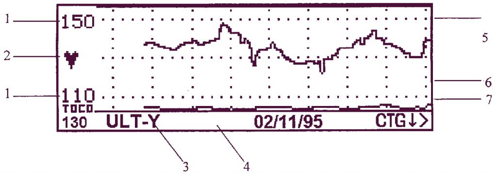
FHR Trace Display mode (CTG mode)
3 4
1 Heart rate range (beats per minute): indicates the range currently displayed.
2 Heart rate lamp: heart-shaped flashing indicator.
3 Channel mode: indicates heart rate channel on display.
4 Display message bar, used for display of interactive messages.
5 Heart rate trace:Displays the active audio channel (or channel 1, yellow, if no audio is selected).If monitoring twin heart rates, only one channel can be displayed at a time.
6 Contractions trace, compressed.
7 CTG ↓ >: this menu pointer changes title and function. See below, Scrolling thetrace and returning to the alphanumeric display below.
Scrolling the trace and returning to the alphanumeric displayThe fetal heart rate trace is initially displayed over the range 110-150bpm. The menupointer in the display message bar reads [CTG >].
To scroll the display vertically:1 Press the Enter button next to the menu pointer.
The display will show the trace over the range 80-120bpm.The menu pointer will then read [CTG >].
2 Press the Enter button next to the menu pointer.The display will show the trace over the range 140-180bpm.The menu pointer will then read [ALPHA >].
3 Press the Enter button next to the menu pointer.The display will return to Alphanumeric display mode.
To scroll the display horizontically, press the Clinical Event marker button [ ].
1
2
1
5
67

Sonicaid Team Operator’s Manual
28
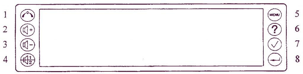
1.12 The Team Keypad
There are eight buttons on the Team display panel. Their primary functions are:1 Toco zero: zeroes the external Toco (contractions) transducer or IUP catheter.2 Volume control up3 Volume control down4 Channel select5 Menu access6 Display Help page7 Clinical event marker8 Enter: confirms an entry or switches display modes
1
2
3
4
5
6
7
8

Sonicaid Team Operator’s Manual
29
2 Getting Started
2.1 Summary of recording procedure
Setup1 Place transducer belts across the bed or chair.2 Make the patient comfortable in a semi-recumbent or sitting position.
Preparing the Team1 Switch on. The on/off switch is on the rear of the base unit.2 Check paper. Is there sufficient paper for the monitoring session? Make sure the
printer platen is securely closed.3 Connect transducers. The plugs and sockets are colour-coded; the display confirms
transducer connection.
Transducer placement1 Palpate the abdomen to determine fetal lie and position.2 Position the Toco transducer (pink) centrally, halfway between fundus and
umbilicus. Do not use gel. Secure with belt and buckle.3 Zero the Toco. Make sure the uterus is relaxed, then press the Toco zero button.
The 10% baseline is displayed.4 Gel the ultrasound transducer (yellow). Place it on the abdomen so as to obtain a
clear heart sound. Secure with belt and buckle.5 Check that the fetal heart rate is clear, and distinct from the maternal pulse rate
taken at the mother’s wrist. Note the maternal pulse rate on the chart paper.Optimum signal quality for the fetal heart rate is shown by 3 bars on the display,with a flashing heart at each beat.
6 Adjust the volume using the volume up and down keys.7 Connect the fetal event marker to the socket on the rear panel. Show the patient
how to use it.

Sonicaid Team Operator’s Manual
30
Using the printer1 To switch the printer on, press the button on the printer front panel.2 To fast forward the paper, press and hold down the printer button.3 To stop the printer, press the printer button again.
Using the second ultrasound transducer for twins1 Connect the second ultrasound transducer (blue) to the Team. The display
switches to twin heart rate display.2 Place both ultrasound transducers on the patient’s abdomen in the optimum
position. Use the blue ultrasound transducer to monitor the first, presenting twin.3 Make sure each fetal heart rate is from a separate fetus. See Section 3.4. If in doubt,
ask for assistance. Secure the ultrasound transducers with belts and buckles.4 To select Audio, press the bottom left button on the keypad. The active audio
channel is highlighted on the display.
Monitoring fetal ECGUsing a Sonicaid scalp electrode:1 Put electrode gel on the base of the leg plate, then strap the leg plate to the
patient’s thigh. Secure with the belt.2 Connect the FECG lead to the Team.3 Once the membranes are ruptured, attach the electrode to the fetus as described
in the electrode instructions.4 Connect the electrode leads to the leg plate. Make sure a good signal is
maintained.5 Wait for the signal to stabilize and a clear fetal heart rate to be displayed on the
Team base unit display. Then adjust the volume control.
Using a Safelinc electrode:1 Attach the FECG lead to the mother’s leg.2 Once the membranes are ruptured, attach the FECG electrode to the fetal pre-
senting part.3 Connext the FECG electrode to the FECG lead.4 Wait for the signal to stabilize and a clear fetal heart rate to be displayed on the
Team base unit display. Then adjust the volume control.
See also Section 3.3.

Sonicaid Team Operator’s Manual
31
2.2 The Team printerThere are three Team printers available:Standard Thermal printer for a continuous paper record of monitored data.Care * With analysis for use during the antepartum period. The analysis
measures fetal heart rate parameters, performs a test against criteriathat define a normal record, and highlights any abnormalities.
Trend * With analysis for use during the intrapartum period. The analysismeasures fetal heart rate parameters at regular intervals, identifyingsuspicious fetal heart rate trends.
* Sonicaid Trend is not available for sale in the USA and Canada.
The procedures described here on trace annotation, loading printer paper and printeroperation apply to all three types of printer. See Chapter 6 Care Printer and Chapter 7Trend Printer for specific information on these two types.
PaperThe printer uses a plain, thermal paper pack (part number 8400-8003). Use onlySonicaid paper. The use of non-approved paper may result in poor qualityprinting or damage to the printer, and could invalidate the printer warranty.
Horizontal scale (print speed)The printer has three speeds: 1 cm/min, 2 cm/min and 3 cm/min. The following tableshows the default print speed in different countries:
1 cm/min 3 cm/min
North America (USA and Canada)
Europe and the rest of the world
To change the print speed, see section 2.5.

Sonicaid Team Operator’s Manual
32
Vertical scaleThe printer’s vertical scale can be 20 bpm/cm or 30 bpm/cm. The following tableshows the default scale in different countries:
20 bpm/cm 30 bpm/cm
North America (USA and Canada)
Europe and the rest of the world
To change the vertical scale, see section 2.3.
2.3 Trace annotation
Trace headerWhen the printer is switched on, a header is printed before the trace data and grati-cule. The header includes user name, date and time, and patient details (if entered).
GraticuleThe graticule is printed at the same time as the trace data, with a 5 bpm or 10 bpmgrid. Set printer switch 2 up for 5 bpm, down for 10 bpm.
Fetal heart rate scaleSet printer switch 4 down for 20 bpm/cm (range 50–210 bpm), or up for 30 bpm/cm(range 30–240 bpm).

Sonicaid Team Operator’s Manual
33
Twin fetal heart ratesSet switch 3 down to print twin fetal heart rate traces superimposed on a full-widthfetal heart rate scale, or up to print side-by-side on two separate fetal heart ratescales.
In side-by-side printing, the primary channel (ULT-Y) is printed on the top scale, thesecondary channel (ULT-B or FECG or MECG*) below. The FHR range depends on thescale setting:
20 bpm/cm 30 bpm/cm100–180 bpm 60–180 bpm
In full-width printing, the primary channel (ULT-Y) is printed as a solid line, thesecondary channel (ULT-B or FECG or MECG*) as a dotted line.
* MECG is not available in the USA and Canada.
Contractions scalesWhen using an external Toco transducer, the contractions scale is 0–100%, relativeunits. When using an intrauterine pressure catheter, the contractions scale is 0–100mmHg or 0–15 kPa, depending on the units of measure selected.
Trace annotationThe printer automatically annotates the trace with the following information:
Heart rate scaleContractions scaleMonitoring modeDate and timePaper speedSignal loss %
Annotation occurs when the printer is switched on, and then at 10-minute intervals (at1 cm/min) or 5-minute intervals (at 2 or 3 cm/min). Each hour is divided into 5-minuteor 10-minute segments starting on the hour, so the second annotation may not printfor up to 19 minutes.
Signal loss is expressed as a percentage over the period between annotations.

Sonicaid Team Operator’s Manual
34
2.4 Loading printer paper
1 Press the release-button beneath the left edge ofthe printer platen.
2 Lift the platen to the left and off the top of theprinter.
3 Place the pack of paper in the compartmentbeneath. (The top side of a new pack of paper isidentified by the message ‘LOAD PACK’, and anarrow pointing to the right. For a partly-used pack,align the blue marks on the pack with the bluemarks on the compartment.)
4 Pull two folds clear of the chart printer, to the right.5 Then fold them back to the left, across the top of
the platen, as it is fitted at a downwards angle tothe right.
6 If necessary, adjust the paper positioning betweenthe sides of the paper channel and press down onthe left edge of the platento latch it.
If, after a period of use, the print quality is poor, checkthat the platen is closed. If still poor, clean the printhead as detailed in the Technical Maintenance section.

Sonicaid Team Operator’s Manual
35
2.5 Printer operationMake sure the printer has sufficient paper for the monitoring session. Ensure theprinter platen is securely closed.
Turning the printer on1 Press the printer button once.2 The indicator in the button lights up and the printer starts.3 The trace header is fast printed.
Printer speedSet the printer setting switches as follows:
Speed Switch 5 Switch 61 cm/min Down Down2 cm/min Up Down3 cm/min Up Up
Turning the printer off1 Press the printer button once.2 The printer fast forwards a little way to allow the paper to be torn.3 The indicator in the button turns off and the printer stops.
Fast forwardPress and hold the printer button. The printer fast forwards for as long as you holdthe button down.

Sonicaid Team Operator’s Manual
36
2.6 Team menu systemTo see the menu, press [MENU] (top right on the Team keypad).
<<<TIME/DATE NEXT>>>
<<<ALARM
<<<ANNOTATE ELAPSED TIME>>>
EXIT>>>
Using the Team MenuEach menu item has arrows (>>>) pointing at the the buttons on the Team keypad.To select a menu item, press the keypad button indicated by the arrows.
Using a menu to enter dataAn example data entry screen is shown below:
<<<123456 OPQRSTU>>>
<<<7890./_ VW XYZ>>>
<<<ABCDEFG EXIT>>>
<<<HIJKLMN SAVE>>>
Numbers and letters are arranged in groups. To enter a character:1 Press the button for the group that contains the character.2 The display now shows this group, with one character against each keypad
button.3 Select the required character.

Sonicaid Team Operator’s Manual
37
2.7 User nameYou can enter a hospital or clinic name (maximum 13 characters) to be printed onthe header of the trace.
Entering a User Name1 Press [MENU] three times.2 Press [USER NAME].3 Enter the hospital or clinic name.4 When done, press [SAVE].5 Team asks IS THIS CORRECT?
If it is correct, press [ACCEPT]. If not, press [RE-ENTER].
2.8 Date and timeTime and date are printed on the trace and shown on the Team display message bar.
To reset the date and time1 Press [MENU] once.2 Press [TIME/DATE].3 Press [NEXT] to move the cursor to the right and highlight the digit you want to
change. Press [DELETE] to move the cursor to the left.4 Enter the required time.5 When done, press [NEXT] until Team asks IS THIS CORRECT? If it is correct, press
[ACCEPT]. If not press [RE-ENTER].6 Enter the date in the same way.
The date format, European or USA, depends on the language selected. See Section2.10, Changing Language.

Sonicaid Team Operator’s Manual
38
2.9 VersionProvides information about the software version and facilities installed in your Team.
1 Press [MENU] three times.2 Press [VERSION]. At the top of the display Team shows the version of software
fitted, and the amount of data storage available (in minutes).For an explanation of [RECONFIGURE], see ‘Changing language’, below.
3 Press [EXIT].
2.10 Changing languageCAUTION: if you reconfigure Team, any records held in the store are deleted,and all defaults are reset to factory-set defaults.
Team menus are available in different languages. To change the choice of language:1 From the [VERSION] Menu, select [RECONFIGURE].2 Team displays a message:
EXIT, THEN TURN UNIT OFF TO RECONFIGURE.
3 Select [EXIT].4 Switch off Team, then switch on again.5 Team now shows the available languages. Select the language you want.
Use the button [ >>>] to scroll through the list and see more choices.
Note: if a selected language is not available, the Team defaults to English.

Sonicaid Team Operator’s Manual
39
2.11 Entering Patient DetailsYou can enter the Gestation Period, Patient Name and Patient Reference Numberinto the Team. These details are then printed on the header of the trace. The detailsare not saved when the Team unit is switched off.
To add patient details1 Press [MENU] once.2 Select [ANNOTATE].3 Enter the Gestation Period as the number of weeks followed by the number of
days. If you enter weeks only, 0 days is assumed.Press [NEXT] to move the cursor to the right. Press [DELETE] to move the cursorback to the left.
4 When done, press [NEXT] until Team asks IS THIS CORRECT? If it is correct, press[ACCEPT]. If it is not correct, press [RE-ENTER].
5 Enter the Patient Name (maximum 13 characters). When done, press [SAVE]. Teamasks IS THIS CORRECT?If it is correct, press [ACCEPT]. If not, press [RE-ENTER].
6 Enter the Patient Reference Number (maximum 13 characters). When done, press[SAVE]. Team asks IS THIS CORRECT?If it is correct, press [ACCEPT]. If not, press [RE-ENTER].
7 Team displays the patient details entered.If they are correct, press [ACCEPT]. If not, press [RE-ENTER].
To edit patient details1 Press [MENU] once.2 Press [ANNOTATE].3 Team displays the patient details. To edit, press [RE-ENTER].
To remove patient detailsSwitch the Team unit off, then on.

Sonicaid Team Operator’s Manual
40
3 Monitoring
3.1 Ultrasound transducers1 Connect the yellow transducer to the yellow socket on Team.2 Place the belt around the abdomen, and secure it with the buckle.3 Apply Aquasonic coupling gel liberally to the face of the transducer. Palpate the
fetus and position the transducer on the abdomen over the fetal site. Move itslowly until the characteristic hoof-beat sound of the fetal heart is heard.
4 Check that the signal quality indicator shows at least two bars, and preferablythree.Check that the fetal heart pulse lamp flashes with each fetal heartbeat.
5 Clip the ultrasound transducer through one of the three positioning holes on thebuckle so that it is retained in the optimum fetal heart signal position.
6 Adjust the sound level with the volume control buttons at the left side of thedisplay.
Procedure for twins (Team Duo/IP)1 Palpate the abdomen and ascertain the lie of each fetus.2 Place the yellow transducer on ‘twin two’, ensuring a good fetal heart rate signal.
Secure the transducer with a belt.3 Place the blue transducer over ‘twin one’, again ensuring a good fetal heart rate
signal. Secure the transducer with a belt.4 Check carefully that the two heart rates are different. If you have not positioned
the transducers correctly, it is possible to record the same FHR twice.
Hints on useMake sure the transducer is placed in the optimum position. Avoid positions withstrong placental sounds (swishing) or fetal cord pulse (indistinct pulse at fetalrate).If the fetus is in the cephalic presentation and the mother is supine, the clearestheart sound will normally be found on the midline below the umbilicus.It is not possible to monitor the fetal heart rate unless an audible fetal heartsignal is present. To distinguish the fetal pulse from the maternal pulse, feel themother’s pulse during the examination, or use the Team’s Maternal ECG* facility(optional on Team IP only).
* Not available in the USA and Canada.

Sonicaid Team Operator’s Manual
41
False recording of low baseline FHRWhen monitoring a low baseline FHR using Doppler ultrasound, the heart rate maybe falsely reported. This effect is known as double-counting, and is characteristic of
ultrasound fetal monitoring.
In normal circumstances the atrium and ventricle beat almost simultaneously. Theultrasound reflected from these two chambers is used by fetal monitors to calculatethe FHR. When the FHR is low, at 70-80bpm, there is a longer time interval betweenthe atrial and ventricular contractions. A fetal monitor may take the reflection fromeach chamber as a separate beat and therefore falsely calculate the FHR.
It can also happen, though very rarely, that the monitor double counts signals whichare maternal in origin.
The Sonicaid FM800’s heart rate detection system separates movements of the heartaway from the transducer from those towards the transducer. This helps to correctsome instances of double-counting, but does not entirely prevent it.
How to minimise the chances of double counting occurring1 Always palpate the abdomen and listen to the fetal heart with a Pinard stetho-
scope or hand-held Doppler unit before applying the ultrasound transducers. This
helps to verify the fetal heart and to locate the area where best signal quality canbe expected.
2 Palpate the maternal pulse for one minute simultaneously and record it on theprinted output.
3 Recording a signal for maternal ECG will help to identify any cross-correlationbetween maternal and fetal heart rates.
4 Listen to the fetal heart rate using the FM800 Audio signal. The sound should belike a galloping horse, not a swishing sound from maternal vessels.

Sonicaid Team Operator’s Manual
42
Transducer buckle and belt attachment
Transducer positioning
Toco transducer
Ultrasoundtransducer

Sonicaid Team Operator’s Manual
43
3.2 External Toco (contractions) transducer1 Check that the plastic membrane on the front face of the Toco transducer is
present and undamaged.2 Connect the Toco transducer to the pink socket on Team.3 Place the belt round the abdomen, and secure it with the buckle.4 DO NOT use coupling gel. Wipe off any gel present on abdomen around this area.5 Clip the Toco transducer through one of the three positioning holes on the buckle
so that it is retained on the midline half-way between the mother’s fundus andthe umbilicus.
6 Contractions activity is measured as a percentage of full scale deflection. The con-tractions measurement automatically zeroes to 10%. This can take up to 3 minutes.To set the zero more quickly, if the mother is not experiencing a contraction, press[TOCO ZERO] (top left on Team keypad).
Replacing the membrane on the Toco transducer1 Remove damaged membrane.2 Wipe the transducer face lightly with a cleaning solvent if necessary.3 Strip the backing paper from a new membrane and press it centrally in place.
Self-adhesive membrane

Sonicaid Team Operator’s Manual
44
3.3 Fetal ECG scalp electrode (TeamIP only)
Fetal scalp electrodesSonicaid Products supplies two types of fetal scalp electrode: Safelincelectrodes (FDA-compliant), and Sonicaid electrodes (not FDA-compliant). In the USAand Canada, the use of FDA-compliant electrodes is required by law. In the rest ofthe world, the choice of lectrodes may depend on local legislation.
FDA compliantelectrodes
non-FDA compliantelectrodes
North America (USA and Canada) xEurope and the rest of the world
Caution: follow the instructions for use supplied with the fetal ECGscalp electrode.
Monitoring procedure using Sonicaid electrodes1 Gel the base of the electrode leg plate, then strap the electrode leg plate to the
front of the thigh. Secure with the belt.2 Connect the electrode leg plate plug (blue) to the blue socket on Team.
3 Once the membranes are ruptured, attach the fetal scalp electrode (1400-0160) tothe fetal scalp or the presenting part as described in the electrode instructions.
4 Connect the electrode leads to the leg plate. The polarity of these connections isnot important. Make sure a good signal is maintained.
5 Allow a few minutes for the signal to stabilize and a clear fetal heart rate to bedisplayed on the Team base unit display (2 or 3 bars of the signal quality indicatorshould be lit).
6 Adjust the volume control as necessary.
Monitoring procedure using Safelinc electrodes1 Following the manufacturer’s instructions, attach the FECG lead to the mother’s
leg, using the adhesive pad.2 Once the membranes are ruptured, attach the FECG electrode to the fetal pre-
senting part, following the manufacturer’s instructions.3 Connect the FECG electrode to the FECG lead.4 Allow a few minutes for the signal to stabilize and a clear fetal heart rate to be
displayed on the Team base unit display (2 or 3 bars of the signal quality indicatorshould be lit).
5 Adjust the volume control as necessary.

Sonicaid Team Operator’s Manual
45
Connection diagram for Sonicaid electrodes
FECG socket:pin 1 M REFpin 2 FECG REFpin 3 FECG electrode
Key:1 FECG socket on
FM8002 Red3 Green4 M REF5 Red6 Black7 FECG electrode8 ECG REF
Connection diagram for Safelinc electrodes
FECG socket:pin 1 M REFpin 2 FECG REFpin 3 FECG electrode
Key:1 FECG socket on
FM8002 M REF3 FECG REF4 FECG electrode

Sonicaid Team Operator’s Manual
46
3.4 Twin heart rate monitoringSimultaneous monitoring of twins can be done with Team Duo or Team IP base units.
The recommended protocols are:
Twin 1 Twin 2
Team Duo 2.0 MHz transducer 1.5 MHz transducerTeam IP 2.0 MHz transducer 1.5 MHz transducer
or Scalp electrode 1.5 MHz transducer
MonitoringTo hear the audio signal for each twin, press [CHANNEL SELECT] (bottom left on theTeam keypad) The active audio channel is highlighted on the Team display.
If the two heart rates appear similar:Team bleepsThe display shows !CHECK TRACE FOR SAME HEART RATEThe printer prints thissymbol on the trace
Confirm the source of the heart rates you are monitoring.
Chart printing in dual monitoring modeThe Team printer can print the heart rate traces side-by-side or superimposed. SeeSection 1.6, Printer switch settings.
In side-by-side printing, the primary channel (ULT-Y) is printed on the top scale, thesecondary channel (ULT-B or FECG) below.
In full-width printing, the primary channel (ULT-Y) is printed as a solid line, thesecondary channel (ULT-B or FECG) as a dotted line.

Sonicaid Team Operator’s Manual
47
3.5 Intrauterine pressure catheter (contractions)Available only on the Team IP base unit. The interconnecting lead between the baseunit and the intrauterine catheter is not included, but is available as an option.
Team is designed for use with an Intran disposable catheter.
1 Connect the intrauterine pressure (IUP) connecting lead to the pink socket onTeam.
Caution: read the instructions for use supplied with the intrauterinepressure catheter
2 Once the membranes are ruptured, insert the catheter as described in theinstructions. The catheter can be supported with a tape or belt.
3 Zero the transducer as described in the instructions, then zero the Team bypressing [TOCO ZERO] (top left on Team keypad).
4 Ask the patient to cough to confirm optimal placement and function of thetransducer. You should observe a spike in the contractions measurement.
To set IUP units of measure1 Press [MENU] three times.2 Select [kPa/mmHg].3 Choose [kPa] or [mmHg].
3.6 Maternal Heart Rate monitoring(not available in the USA and Canada)
Allows you to check that the heart rate being recorded belongs to the fetus and notthe mother. Available only on the Team IP. The maternal ECG (MECG) lead anddisposable electrodes are not included, but are available as options.
1 Apply self-adhesive disposable electrodes to the mother.As it is only necessary to pick up the maternal pulse and not the ECG complex,placement of the electrodes is not critical, but it is a good idea to have the third,lower electrode placed clear of the diaphragm, as the muscles here are very activein contraction.

Sonicaid Team Operator’s Manual
48
A recommended arrangement of the lectrodes might be:
W
R
B
2 Connect the MECG lead plug (blue) to the blue socket on Team.3 Clip the three flying leads of the MECG lead to the electrodes. They are colour-
coded white, black and red (W, B and R in the diagram above).4 Allow a few minutes for stabilisation and a clear maternal heart rate to be
displayed.5 Adjust the volume control as necessary. The audio signal in this mode is a bleep.
If the maternal and fetal heart rates appear similar:Team bleepsThe display shows !CHECK TRACE FOR SAME HEART RATE
Confirm the source of the fetal heart rate you are monitoring.
3.7 Team connected to FetalCare or System8002Sonicaid FetalCare and Sonicaid System8002 are PC-based antepartum analysissystems. Sonicaid FetalCare is the replacement for Sonicaid System8002. The analysismeasures fetal heart rate parameters, and performs a test against criteria that definea normal record.
You can store a record on the Team monitor, then transfer it to FetalCare or System-8002 for analysis. Or you can connect Team directly to FetalCare or System8002 forreal-time analysis of monitored data.

Sonicaid Team Operator’s Manual
49
Note: analysing twinsTeam can send real-time FHR data for twins to a Sonicaid FetalCare system. If you haveSystem8002, Team can send real-time FHR data from the yellow channel only. In thatcase, you can store the FHR data from the blue channel while you are monitoring, andlater transfer it to the FetalCare or System8002 for retrospective analysis. See Section5, Storing Records.
Connecting Team to FetalCare or System8002Use the Team-to-System8002 interconnecting lead.
1 Connect the lead to the RS232 connector on the rear of the Team base unit.2 Connect the lead to the COM1 port on the rear of the FetalCare or System8002 PC.
Note: for full details of PC connections, and instructions for using the system, see theSonicaid FetalCare User Guide or the Sonicaid System8002 User Guide.

Sonicaid Team Operator’s Manual
50
4 Events and Alarms
4.1 Recording fetal movement eventsFetal movements are recorded by the mother operating a hand-held push-buttonevent marker. When an event is noted, a solid triangular event mark is printed at thetop of the fetal heart rate trace. The Team beeps, if the audible beep is switched on.
1 Connect the event marker to the jack socket on the rear of the Team base unit.2 Give the event marker to the mother. Tell her to press the button every time a
fetal movement is felt.
To turn the audible beep off or on1 Press [MENU] once.2 Select [ALARM].3 Press [FETAL MOVEMENT].4 Select [SILENT EVENT] or [AUDIBLE EVENT].
4.2 Actogram
Note: the Actogram feature is not available in the USA and Canada.
Actogram uses the low-frequency content of the signal from the 1.5 MHz ultrasoundtransducer to detect fetal movements, and give an activity profile of the fetus.
WARNING: ACTOGRAM IS NOT INTENDED FOR USE DURING LABOUR.
Recorded activity represents fetal movements (breathing, limb and trunk movement)or non-fetal movements (transducer movement, maternal coughing or other move-ment).
The Actogram value can be printed as a line graph on the contractions trace, or asfetal event marks above the trace, or both. An event mark is printed every time theamplitude goes above a set threshold. The default threshold is 40% of full scaledeflection, but it can be set to any value in the range 0-99%.

Sonicaid Team Operator’s Manual
51
In a study of 14 near-term normal fetuses with the threshold set at 40%, the sensi-tivity and specificity of the Actogram function (compared with scanner-identifiedbreathing, limb movement and trunk movement) were 96% and 68% respectively.This data is published with the kind permission of Professor David James of theDepartment of Obstetrics and Gynaecology, Queens Medical Centre, Nottingham.
Actogram setup menu1 Press [MENU] twice.2 Select [ACTOGRAM].3 To increase or decrease the sensitivity of Actogram’s detection of fetal movement,
use the [SENSITIVITY] button.
<<<ULTRASOUND ACTIVITY MARKS ARE OFF
<<<ULTRASOUND ACTIVITY GRAPH IS OFF
<<<SET ACTOGRAM THRESHOLD 40
<<<SENSITIVITY EXIT>>>
Changing the Actogram display settingFrom the Actogram setup menu:1 Press [ACTOGRAM ACTIVITY MARKS] to turn event mark printing on and off.2 Press [ULTRASOUND ACTIVITY GRAPH] to turn graph printing on and off.
Changing the Actogram thresholdFrom the Actogram setup menu:1 Press [SET ACTOGRAM THRESHOLD].2 Enter a new value.
The required threshold may depend on whether the trace is showing a high incid-ence of artefact. It is recommended to set the threshold between 40 and 60%.
3 Observe the Actogram trace for a short period to see if the setting is satisfactory.

Sonicaid Team Operator’s Manual
52
Data storageTeam stores Actogram event marks when it stores an FHR record. It does not storethe Actogram activity graph and threshold value.
TwinsActogram works from information collected only from the 1.5 MHz transducer, but itmay also sometimes detect fetal movements from the other twin. To minimise thiseffect, position the 1.5 MHz and 2.0 MHz transducers as far apart as possible andadvise the mother to remain as still as she can.
Actogram graph and event marksThe following illustration shows Actogram graph and event marks superimposed onthe contractions trace.
1 2
1 Actogram event marks 2 Actogram graph

Sonicaid Team Operator’s Manual
53
4.3 Recording clinical eventsClinical events can be recorded either as a solid square event mark printed at thebottom of the fetal heart rate trace, or as a clinical event note printed at the top ofthe fetal heart rate trace. Event notes are selected from topic-related menus on theTeam display. They can only be entered when the printer is active.
To enter a clinical event note1 Press the Clinical Event button [ ] on the Team keypad.2 Select a note topic from the note main menu.
<<<DRUGS OTHER>>>
<<<POSITION ANTENATAL>>>
<<<MEMBRANES REASON>>>
<<<PROCEDURES EXIT>>>
3 Select a note from the topic sub-menu.
To enter a clinical event mark1 Press the Clinical Event button [ ] on the Team keypad.2 Select [EXIT] from the note main menu.
Note: when Team Care analysis is being run on twins, the Clinical Event button isused to record movement of the second fetus, as this is required for the analysis. Inthis case pressing the Clinical Event button prints a solid triangular fetal event mark.

Sonicaid Team Operator’s Manual
54
4.4 Alarms
Alarm setup menu1 Press [MENU] once.2 Select [ALARM].
<<<SIGNAL LOSS
<<<LOW FHR FETAL MOVEMENT>>>
<<<HIGH FHR
EXIT>>>
Signal loss alarmYou can set a signal loss threshold above which an alarm will occur. This threshold isa percentage of the last 5-minute period. With a setting of 20%, for example, one-minute of signal loss in 5 minutes will trigger the alarm. This alarm is only activewhen the printer or store is active.
To set a signal loss alarm:1 From the Alarm setup menu press [SIGNAL LOSS].2 Select [ALARM ON SILENT] or [ALARM ON AUDIBLE].
If you set a silent alarm, and the alarm is triggered, a notification appears on thedisplay message bar, but the Team does not beep.
3 Enter the % signal loss required.4 Team asks IS THIS CORRECT? If it is correct, press [ACCEPT]. If it is not correct, press
[RE-ENTER].
To turn the signal loss alarm off:1 From the Alarm setup menu press [SIGNAL LOSS].2 Select [ALARM OFF].
Low and high FHR alarmsYou can set fetal heart rate thresholds such that an alarm occurs if the signal remainsabove or below the threshold for a specified time (known as the ‘delay time’). Thesealarms are only active when the printer or store is active.

Sonicaid Team Operator’s Manual
55
To set an FHR alarm:1 From the Alarm setup menu press either [LOW FHR] or [HIGH FHR].2 Select [ALARM ON SILENT] or [ALARM ON AUDIBLE].
If you set a silent alarm, and the alarm is triggered, a notification appears on thedisplay message bar, but the Team does not beep.
3 Enter the heart rate threshold required.4 Team asks IS THIS CORRECT?
If it is correct, press [ACCEPT]. If not, press [RE-ENTER].5 Enter the delay time required.6 Team asks IS THIS CORRECT?
If it is correct, press [ACCEPT]. If not, press [RE-ENTER].
To turn an FHR alarm off:1 From the Alarm setup menu press either [LOW FHR] or [HIGH FHR].2 Select [ALARM OFF].
Timer alarmsYou can set a timer to tell you when a given period of time (from 1 to 99 minutes)has elapsed. The timer starts when you start storing or printing, and restarts if youreset the alarm while storing or printing. When the set time has elapsed, an alarmoccurs.
To set the timer:1 Press [MENU] once.2 Select [ELAPSED TIME].3 Select [ALARM ON SILENT] or [ALARM ON AUDIBLE].4 Enter the period required.5 Team asks IS THIS CORRECT?
If it is correct, press [ACCEPT]. If not, press [RE-ENTER].
To turn the timer off:1. Press [MENU] once.2. Select [ELAPSED TIME].3 Select [ALARM OFF].
Acknowledging an alarmWhen an alarm occurs, a notification appears on the display message bar. The Teamalso beeps, if you set [ALARM ON AUDIBLE], but not if you set [ALARM oN SILENT].
To cancel the alarm, press the [ENTER] key at the bottom right of the Team keypad.

Sonicaid Team Operator’s Manual
56
5 Storing Records
5.1 StoringYou can store data electronically in the Team base unit. Stored records can laterbe reviewed on the Team display, printed, or transferred to Sonicaid FetalCare orSystem8002 by direct cable connection or by modem (Team DM only).
Team can store only one fetal heart rate channel at a time, together with the contrac-tions information and fetal event marks. You can select which channel to store.
Storage spaceThere are two limitations on the space available for storing records: number ofrecords and total recording time.Number of records: the maximum number of records Team can store is 14.Total recording time: Team can store up to 6 hours’ worth of recordings. Since themaximum length of a record is 65 minutes, this means there may be space for fewerthan 14 records, if there are several long records.
If there is not enough space for a record, Team deletes the oldest record, or records,until there is enough space. Team can delete a record only if it has already beenprinted or transferred to Sonicaid FetalCare or or System8002. If no records are avail-able for deletion, Team displays the message STORE FULL in the display message bar.Use the [REVIEW] menu to decide which records to delete.
Patient detailsWhen you store a record, you should enter patient details so that the stored recordcan be identified with that patient. Before storing, Team asks you to enter thesedetails (see Entering Patient Details). All stored records have time and date detailssaved.
Note: Team can have a 13-character patient reference number. Sonicaid FetalCareand System8002 store only the first 8 characters of this number.

Sonicaid Team Operator’s Manual
57
Auto Store detailsA record can be stored without entering patient details. Team labels the record withthe number ASNN, where NN is a 2-digit number starting at 01 and counting up as
new records are stored. Patient details can be added to these records after stoppingstorage.
Note: you must enter full patient details if you wish to transfer the record to SonicaidFetalCare or System8002.
Selecting which channel to store1 Press [MENU] twice.2 Select [SELECT STORE].3 Team shows the current channel selected.4 Select the required channel.5 When done, press [EXIT].
Start storing1 Press [MENU] twice.2 Select [STORE].3 Team asks DO YOU WISH TO ANNOTATE? To use Auto Store annotation, press
[STORE]. To enter patient details, press [ANNOTATE].4 Enter patient details.5 When done, press [STORE].
Stop storing1 Press [MENU] twice.2 Select [STOP STORING].3 If you used Auto Store annotation, Team asks DO YOU WISH TO ANNOTATE?
To enter patient details now, press [ANNOTATE]. Otherwise press [EXIT].4 Enter patient details.5 When done, press [EXIT].

Sonicaid Team Operator’s Manual
58
5.2 Selecting a stored record for reviewStored records can be reviewed on the Team display, printed, or transferred toSonicaid FetalCare or Sonicaid or System8002 by direct cable connection. Using TeamDM you can also transfer records via a modem.
To select a record for review:1 Press [MENU] twice.2 Select [REVIEW].3 A list of stored records is displayed, the most recent at the top. To the left of the
list is a selection arrow [ ]. You can move this down then up the list by pressingthe button with [ ] next to it.‘P’ to the left of a record means it has been printed.‘S’ means it has been transferred to Sonicaid FetalCare or System8002.
4 Highlight the record for review with the selection arrow, then press [SELECT].5 The patient details for the selected record appear on the Review Options menu.
From here choose to display, print or transfer the record to Sonicaid FetalCare orSystem8002. You can also edit the patient details, or delete the record when youhave finished with it.
5.3 Displaying a stored recordOnce a stored record has been selected, you can review it on the Team display:
1 From the Review Options Menu, press [DISPLAY].
2 To scroll through the display, press [ ].To change the displayed range, press [↵ ].
5.4 Printing a stored recordOnce a stored record has been selected (see Section 5.2 above), you can print it onthe Team printer. The printer runs faster than for on-line printing, at a speed of10cm per minute.
1 From the Review Options menu press [FAST PRINT].2 Team asks PRINT THIS DATA?
To print, press [FAST PRINT]. Otherwise press [EXIT].3 To stop printing, press [STOP PRINTING].

Sonicaid Team Operator’s Manual
59
5.5 Transferring a stored record toSonicaid FetalCare or System8002
You can transfer a selected record to a Sonicaid FetalCare or Sonicaid System8002 foranalysis either by direct cable connection or (using Team DM) by modem. This sectiondescribes direct cable connection.
For transfer by modem, see Chapter 8 Team DM (Distance Monitoring).
Connecting Team to FetalCare or System8002Use the Team-to-System8002 interconnecting lead.1 Connect the lead to the RS232 interface on the rear of the Team base unit.2 Connect the lead to the COM1 interface on the rear of the PC running the
FetalCare or System8002 software.For full details of PC connections see the Sonicaid FetalCare User Guide or theSonicaid System8002 User Guide.
Transferring a stored record to System80021 System8002: from the MainMenu select [Receive Direct Data].2 From the Team Review Options Menu, press [DIRECT DATA].3 Data transfer starts.4 When the transfer is complete:
On Team, press [PRESS RETURN TO CONTINUE].On the PC running the FetalCare or System8002 software, confirm that thepatient details are correct.
5 System8002 analyses the record.
On a Team DM base unit, the [DIRECT DATA] option on the Review Options Menu isreplaced by a [SEND] option. Press [SEND], then [DIRECT DATA].
Transferring a stored record to Sonicaid FetalCareSee the Sonicaid FetalCare online help.

Sonicaid Team Operator’s Manual
60
5.6 Deleting a stored recordOnce a record has been printed or transferred to Sonicaid FetalCare or System8002, itcan be deleted:
1 From the Review Options Menu, press [DELETE].2 Team asks ARE YOU SURE YOU WANT TO DELETE THIS?3 Press [DELETE].

Sonicaid Team Operator’s Manual
61
6 Care Printer (option)
The Care printer is the printer supplied when you purchase TeamCare.
6.1 OverviewThe Team Care printer has an analysis system for use during the antepartum period.The analysis measures fetal heart rate parameters and performs a test against criteriathat define a normal record. Abnormalities are highlighted.
The analysis is based on more than 48,000 records which have been compared withoutcome, and originates from work carried out by Professor G.S. Dawes and ProfessorC.W.G. Redman at the Nuffield Department of Obstetrics and Gynaecology, The JohnRadcliffe Hospital, Oxford, England. See 6.8 References.
6.2 Intended useThe intended use of Sonicaid Care analysis is to analyse antepartum CTGs (NSTs) inpregnancies from 26 weeks gestation onwards. It can be used on women who areexperiencing Braxton-Hicks contractions, but is not intended for use in establishedlabour as the fetus is then exposed to additional factors such as labour contractions,pharmacological agents, and epidural anaesthesia.
The analysis provided by the Sonicaid Care is intended to assist, not toreplace, the physician’s visual assessment of a trace. As such, Sonicaid
Care is not a diagnosis, but an aid to clinical management. Diagnosis remains theresponsibility of an appropriately qualified physician. Indeed, both the physician’svisual assessment of the trace and the analysis provided by Sonicaid Care should beconsidered within the context of a full clinical assessment before decisions are maderegarding management. Such a clinical assessment may include further tests such asumbilical blood flow velocity waveforms or biophysical profiling.

Sonicaid Team Operator’s Manual
62
6.3 The Dawes/Redman criteriaThe Dawes/Redman criteria are criteria for normality. If a record meets the criteria,this means that as far as the analysis can tell by measuring the features of the trace,the fetus is normal. It is not a guarantee that the baby is healthy, but it does meanthere is nothing in the trace which gives cause for concern. [somebody please checkthat paragraph]
These are the criteria:An episode of high variation, above the first centile for gestational age.No decelerations > 20 lost beats (> 100 lost beats on records longer than 30 minutes).Basal heart rate between 116 and 160 bpm, though a slightly lower or higher ratemay be acceptable after 30 minutes, if all other parameters are normal. This isindicated by one asterisk on the analysis results to show that the fetal heart rate islow or high, but that in the context of the rest of the record, it is acceptable.At least one fetal movement or three accelerations.No evidence of a sinusoidal fetal heart rate rhythm.Short-term variation should be 3 ms or greater.Either an accelerationor variability in high episodes > the tenth centile and fetal movements > 20.
No errors or decelerations at the end of the record.
6.4 Care analysis optionThe maximum record length is 60 minutes. Analysis is performed at 10 minutes, andevery 2 minutes thereafter. If you stop the printer before 10 minutes, no analysis isperformed. You are asked either to confirm that you want to stop, or to continue.
The analysis fits a baseline to the fetal heart rate data collected so far, and from thismeasures accelerations and decelerations. Short-term variation is calculated, andepisodes of high and low variation looked for.
The system compares the calculated results with the Dawes/Redman criteria (criteriafor normality). If the record appears normal, CRITERIA MET appears on the Teammessage bar, and Team gives a single beep. At this point you can stop the analysis,and the printer will produce a report of the analysis results.

Sonicaid Team Operator’s Manual
63
If the criteria are not met, CRITERIA NOT MET is shown, and you should allow theanalysis to continue. If the analysis is still running at 60 minutes, Team ends thisanalysis, prints the results on the trace, and then starts a new analysis. The printercontinues printing throughout. In the results, any abnormalities (showing why thetrace did not meet the criteria) are highlighted with asterisks. See Abnormalities, inSection 6.6.
Note: if the criteria are met, but for some reason you do not stop the analysis, it canvery rarely happen that the results then change to CRITERIA NOT MET. As more data isreceived, a subsequent analysis may re-fit the baseline so that, for example, an episodeof high variation is no longer above the first centile. Such a change is extremely rare,but can occur in a high-risk unit with a baby which is on the borderline betweennormality and abnormality. If this happens, the recommendation is to continuemonitoring until the criteria are met again.
Analysing twinsWhen monitoring twins, using two ultrasound transducers, both channels areanalysed simultaneously. The results for each fetus are identified by the channelmode and colour:
ULT-Y YellowULT-B Blue
Fetal movement events
The mother should try to mark events for each fetus. If she is not sure which fetus ismoving, she should make no marks at all.
The conventional fetal event marker lead marks events on the primary channel(yellow). The Clinical Event marker button on the Team keypad marks events on thesecondary channel (blue). The usual Clinical Event facility is not available in thesecircumstances.
Gestational ageThe analysis takes the gestational age of the fetus into account. Team asks you toenter this information when you start the analysis. Or you may use Annotation topre-enter this and other patient details.

Sonicaid Team Operator’s Manual
64
ActogramEvent marks recorded by the Actogram facility are not used by the Team Careanalysis.
AlarmsDuring analysis the Signal Loss alarm is fixed at 30%. In addition, there is a fixedToco alarm that alerts the user to a constant Toco value for 10 minutes. Once thisalarm has been acknowledged, it will not re-alarm during the same analysis.
Fetal ECG modeSince the analysis is not valid during labour, it does not run on the secondary channelif this is using a fetal ECG scalp electrode.
6.5 Using the analysis
Starting the analysis1 Set up Team as you would to record a normal trace.2 Press [MENU] once. Check that the display says ANALYSIS IS ON. If it says
ANALYSIS IS OFF, then select [TURN ANALYSIS ON].3 Press the printer button once to start the printer.4 Team beeps, and asks you to enter the gestational age of the fetus.5 Enter the gestational age.6 The Team stops beeping, and the printer starts.
Stopping the analysis1 Press the printer button once to stop the printer.2 The trace fast forwards, and the analysis results are printed.
If you stop the printer before 10 minutes, Team says CANNOT ANALYSE. LESS THAN10 MINUTES DATA, and asks CONTINUE PRINT & ANALYSIS?
Select either [HALT PRINTER] or [CONTINUE PRINT].

Sonicaid Team Operator’s Manual
65
Checking analysis progressAfter the first analysis has been performed at 10 minutes, you can check the keyresults by pressing the return button on the keypad indicated by [RESULTS>>>] inthe display message bar. The Team shows the last calculated values for short termvariation, number of minutes of high variation and basal heart rate. An asteriskbeside a figure indicates an abnormal result. See Abnormalities, in Section 6.6.
For twins, the results shown are for the fetus on the currently selected audiochannel. This is confirmed on the display with either ULT-Y or ULT-B. If no audiochannel is selected, the default is the yellow channel.
To turn the analysis offTo record a trace without the analysis:1 Press the printer button once to start the printer.2 When Team asks you to enter the gestational age, select [ANALYSIS OFF].3 The printer then starts without the analysis.
Or:1 Press [MENU] once.2 Select [TURN ANALYSIS OFF].3 Press the printer button to start recording.
By default, the analysis is ON if it was on the last time Team was used, and OFF if itwas off the last time Team was used.
Analysing a stored traceA stored trace can be analysed when it is printed on a Team Care printer. The patientdetails for the stored trace must include the gestational age.

Sonicaid Team Operator’s Manual
66
6.6 The analysis reportWhen the analysis is stopped, the printer produces a report of the analysis results atthe end of the trace. The report shows:
Values for the calculated parametersWhen the Dawes/Redman criteria (criteria for normality) were first metWhether the Dawes/Redman criteria were met at the time the analysis wasstoppedAbnormalities
Reasons for not meeting the criteriaIf the criteria were not met when the analysis was stopped, the reasons are given ascoded numbers alongside the CRITERIA NOT MET message:
Code Reason 1 Basal heart rate outside normal range 2 Large decelerations 3 No episodes of high variation 4 No movements and fewer than 3 accelerations 5 Baseline fitting is uncertain 6 Short-term variation is less than 3ms 7 Possible error at the end of the record 8 Deceleration at the end of the record 9 High-frequency sinusoidal rhythm 10 Suspected sinusoidal rhythm 11 Long-term variation in high episodes below acceptable level 12 No accelerations

Sonicaid Team Operator’s Manual
67
AbnormalitiesDouble asterisks indicate one of the following conditions:
Fetal heart rate < 116 bpm or > 160 bpm on a record of less than 30 minutesDecelerations > 100 lost beats (> 20 lost beats on record of less than 30 minutes)No moves and fewer than 3 accelerationsNo episodes of high variationShort-term variation < 3msNo accelerations, and either < 21 movements per hour or long-term variation in
episodes of high variation below the tenth centileLong-term variation in episodes of high variation below the first centile
A single asterisk indicates one of the following conditions:Short term variation < 4 ms, but ≥ 3msBasal heart rate < 116 bpm or > 160 bpm on a record ≥ 30 minutesDecelerations present, but not meeting the criteria for size or record length
A single asterisk does not necessarily mean that the record cannot pass the criteria.If all other parameters are normal at the 30-minute point, the abnormality could beconsidered to be within acceptable limits to meet the analysis criteria.
Basal heart rate warningsA basal heart rate of 115 bpm or lower triggers a printed warning on the analysisreport:
WARNING: LOW BASAL FHRCHECK THAT FHR DOES NOT CONTINUE TO FALLFETAL MOVEMENTS PRESENT? SINUSOIDAL RHYTHM?

Sonicaid Team Operator’s Manual
68
Example printout of TeamCare trace and analysis report

Sonicaid Team Operator’s Manual
69
Example printout of TeamCare twins analysis results

Sonicaid Team Operator’s Manual
70
6.7 Plotting trend dataPre-printed Trend Graph forms are available in packs of 50, part number 8902-8002.These enable you to produce a plot manually of the key values given in the analysisreport. With other clinical information, these graphs may allow a trend of fetalhealth to be discerned.
The forms allow plotting of:Moves per hourShort-term variationBasal heart rateDeclarative trace (mark a ‘D’ on the graph to indicate this)
This is normally done after four or more records are taken in a 28-day period.
6.8 Analysis parameters and calculations
The baselineThe analysis uses pulse intervals averaged over 1/16 minute to fit a baseline to thefetal heart rate trace. Accelerations and decelerations are measured from this base-line.
The baseline follows slow, but not rapid, changes in the fetal heart rate. It is re-fittedat every analysis, as further information becomes available.
Basal heart rateThe basal heart rate is the mean rate averaged over all periods of low variation. If nolow variation is present, it is derived from a statistical analysis.
The basal heart rate should be between 116–160 bpm. A basal heart rate of 160–170bpm is not sinister antepartum provided that the mean range of the fetal heart ratevariation is within normal limits and there are no large decelerations. A basal heartrate greater than 170 bpm suggests the possibility of fetal infection.

Sonicaid Team Operator’s Manual
71
A basal heart rate less than 105 bpm requires further investigation at once. A fewnormal fetuses at 38–42 weeks gestation have a basal heart rate of 110–115 bpm.The threshold of 115 bpm at which a warning is given is chosen conservatively, togive warning of a compromised fetus in which the fetal heart rate may be fallingprogressively. It is likely that fewer than 1% of analysed records in clinical practicewill come in this category.
AccelerationsThe analysis defines an acceleration as being a rise of 10 bpm or 15 bpm above thebaseline for more than 15 seconds.
The Dawes/Redman criteria (criteria for normality) use the first of these definitions.A count of accelerations meeting both definitions is made on the analysis report.
DecelerationsThe analysis defines a deceleration as being a trough ≥ 10 bpm below the baselinefor more than 1 minute, or ≥ 20 bpm below the baseline for more than 30 seconds.
The area of each deceleration is calculated and expressed in ‘lost beats’. A deceleration> 20 lost beats is regarded as large. A count of decelerations is made on the report.Any deceleration > 50 lost beats is described in detail on the report, and the meanvariation for 3 minutes before and after the deceleration is given.
Short-term variationThe record is divided into one-minute intervals. Intervals containing a deceleration orpart of a deceleration are discarded, as are intervals with high signal loss or artefact.Each remaining interval is divided into sixteen epochs of 3.75 seconds. The meanfetal heart rate for each epoch is determined and expressed as a pulse interval inmsecs. The difference between adjacent epochs is calculated.
The short-term variation is calculated as the mean of these adjacent epoch pulseintervals over the record during all valid minutes.

Sonicaid Team Operator’s Manual
72
The measurement of short-term variation, in the absence of episodes of highvariation, is independent of basal fetal heart rate, and correlates with thedevelopment of metabolic acidaemia and intrauterine death as follows:
STV % likelihood of metabolic(ms) acidaemia or intrauterine death> 4 0
3.5-4.0 83.0-3.5 292.5-3.0 33< 2.5 72
STV has been shown to be an excellent indicator of fetal well-being.
Episodes of high and low variationAn episode of high variation is defined as a section of the trace where the one-minute peak-to-peak variation is above a given threshold for 5 out of 6 consecutiveminutes. An episode of low variation is defined as a section of the trace where theone-minute peak-to-peak variation is below a given threshold for 5 out of 6 consec-utive minutes.
The threshold for high is defined by a pulse interval of 32 ms, and the threshold forlow by a pulse interval of 30 ms. The variability for each episode is expressed in beatsper minute, and is independent of the basal heart rate.
High variation occurs when the fetus is in an active sleep phase, and low variationwhen it is in quiet sleep. As the fetus matures, episodes of high variation increase,and episodes of low variation decrease. One of the Dawes/Redman criteria is forthere to be an episode of high variation where the peak-to-peak variation for theepisode is greater than the first centile, when corrected for gestational age.

Sonicaid Team Operator’s Manual
73
Calculating peak-to-peak variationThe fetal heart rate record is analysed in one-minute intervals. Intervals containing adeceleration or part of a deceleration are discarded, as are intervals with high signalloss or artefact. For each remaining interval the maximum to minimum variation inthe fetal heart rate within that minute is calculated. The peak-to-peak variation isdefined as the maximum positive to maximum negative excursion from the fittedbaseline.
Fetal movementsFetal movements recorded by the mother are counted and quantified per hour. Thisnumber is given on the analysis report. In a normal trace, movements will be morefrequent during episodes of high variation than in episodes of low variation.
Fetal movements are recorded for twins’ traces, but not divided between twin 1 andtwin 2.
ContractionsThe analysis defines a contraction as a rise in relative uterine pressure measurementto greater than 16% from the baseline for 30 seconds or more. A count of contrac-tions meeting this definition is made on the analysis report.
Signal lossThe system monitors the loss of fetal heart rate signal. Where there is a gap in thetrace due to signal loss, the analysis interpolates a straight line through the missingsection when fitting the baseline. When the analysis is running, the signal loss alarmis fixed at 30%. The signal loss as a percentage of the whole record is given on theanalysis report. The analysis is not able to interpret the data if there is signal loss> 80%.
If there is signal loss > 50% during either an acceleration or a deceleration of greaterthan 20 lost beats, the acceleration or deceleration is not counted.
ErrorsSignal artefacts are detected by the analysis, and counted as signal loss.

Sonicaid Team Operator’s Manual
74
6.9 ReferencesSome publications on computerised fetal heart rate analysis:
Street P, Dawes GS, Moulden M, Redman CWG‘Short-term variation in abnormal antenatal fetal heart rate records’American Journal of Obstetrics and Gynecology, 1991, 165:515-523
Nijhuis IJM, ten Hof J, Mulder EJH, Nijhuis JG,Narayan H, Taylor DJ, Westers P, Visser GHA‘Numerical fetal heart rate analysis: nomograms, minimal duration of recording andinterfetal consistency’Prenatal and Neonatal Medicine, 1998, 3:314-322.
Burch D‘Computerised measurement of fetal heart rate variation in a case of fetomaternalhaemorrhage’British Journal of Obstetrics and Gynaecology, 1994, 101:1089-1090
Pardey J, Moulden M, Redman CWG‘A computer system for the numerical analysis of nonstress tests’American Journal of Obstetrics and Gynecology, 2002, 186:1095-1103.
Brown R, Patrick J‘The nonstress test — how long is enough?’American Journal of Obstetrics and Gynecology, 1981, 141:646-651.
Blumofe KA, Broussard PM, Walla CA, Platt LD‘Computerized versus visual analysis of fetal heart rate — a reduction in testing time.’American Journal of Obstetrics and Gynecology, 1992, 166:415

Sonicaid Team Operator’s Manual
75
7 Trend Printer (option)
The Trend printer is the printer supplied if you purchase TeamIP Trend.
Note: Sonicaid Trend analysis is not approved for sale in the USA and Canada.
7.1 IntroductionThe Team Trend printer incorporates an analysis system for use during the intra-partum period. The analysis, which provides measurement of fetal heart rate para-meters at regular intervals, offers a new way of describing the attributes of the tracethat is quantitative and not qualitative. It is not intended as a replacement for skilledvisual interpretation of the trace.
Used with continuous fetal monitoring, it allows you to assess long-term changes inthe fetal heart rate pattern. No guidelines on interpretation or limits of normalityare provided. Instead, the clinician can use the numeric values to identify and quant-ify the relative changes in fetal heart rate parameters over a period of time.
A numerical description of the trace enables direct comparison between differenttraces. It also provides training support for trace interpretation, and readily availabledata for clinical research projects.
The analysis is an extension of the antepartum analysis work originated by ProfessorG.S. Dawes, Professor C.W.G. Redman and M. Moulden at the Nuffield Departmentof Obstetrics and Gynaecology, John Radcliffe Hospital, Oxford, England.
IMPORTANTThe analysis provided by the Team Trend printer generates parameters describingthe fetal heart rate on the record. The interpretation and diagnosis of the recordremains the responsibility of the appropriately qualified medical staff.
WARNING: the analysis is valid only during the first stage of labour.

Sonicaid Team Operator’s Manual
76
7.2 Team Trend analysisAnalysis is performed at 15 minutes, and then every 15 minutes thereafter. Theanalysis fits a baseline using the last 60 minutes of fetal heart rate data collected,then calculates the following parameters:
Baseline heart rate (bpm) for the last 60 minutesBaseline heart rate (bpm) for the last 15 minutesShort-term variation (msecs) for the last 60 minutesDeceleration size (beats) for the last 60 minutesDeceleration size (beats) for the last 15 minutes
Note: the user may choose to show or hide results for deceleration size.
Confidence indicatorThe analysis provides a confidence indicator showing the reliability of the baselinefit, and hence the fetal heart rate parameters. Confidence is indicated as High,Medium or Low, shown as H, M or L.
If the confidence indicator is Medium or High the analysis results will reliably reflectthe fetal heart rate pattern. If the confidence indicator is Low, the results should beinterpreted in relation to the appearance of the trace, and only used if it is thoughtthat they are a sensible reflection of the visually assessed pattern.
Analysing twinsWhen monitoring twins, both channels are analysed simultaneously.

Sonicaid Team Operator’s Manual
77
7.3 Using the analysis
Starting the analysis1 Set up Team as you would to record a normal trace.2 Press the printer button once to start the printer. This starts the analysis as well.
Stopping the analysisTo stop the printer, press [PRINTER], then [HALT].If you press [PRINTER] by accident, press [CONTINUE] to resume.
Turning the analysis offTo record a trace without the analysis:1 Press [MENU] once.2 Select [TURN ANALYSIS OFF].3 When done, press [EXIT].4 Press the printer button to start recording.
Turning the analysis onTo turn the analysis on again:1 Press [MENU] once.2 Select [TURN ANALYSIS ON].3 When done, press [EXIT].
Deceleration size parameterThe default is for deceleration size results not to be printed or displayed.
To print and display the deceleration size:1 Press [MENU] three times.2 Select [TURN DECEL ON].3 When done, press [EXIT].

Sonicaid Team Operator’s Manual
78
7.4 Analysis results
Printed resultsWhen an analysis has been performed, the parameter values and confidence indicatorare printed on the contractions section of the trace. A key to the parameters is printedon the trace header, and again three minutes before the end of each 60-minuteperiod. See the example in Figure 7.1.
The 60-minute values are available after the first hour. Until then the results show ‘NA’.
Signal lossIf signal loss is > 50%, the results show ‘SL’.
Twins resultsBoth channels are analysed simultaneously. The results for each fetus are identifiedby the channel mode and colour:
ULT-Y YellowULT-B or FECG Blue
Displayed resultsAfter each analysis, the results are also shown on the Team base unit. The displayreturns to the fetal heart rate display after two minutes, or when you press [EXIT].
TIME 21:0660 MIN BASELINE 13915 MIN BASELINE 14460 MIN STV 7.860 MIN DECEL 35015 MIN DECEL 90CONFIDENCE H<<<TREND ULT-Y EXIT>>>
If you are analysing twins, the results shown are for the fetus on the currentlyselected audio channel, shown on the display as ULT-Y or ULT-B/FECG. If no audiochannel is selected, the display defaults to the primary (yellow) channel.

Sonicaid Team Operator’s Manual
79
Printout showing Team Trend analysis results

Sonicaid Team Operator’s Manual
80
7.5 Viewing trend dataTo see a trend of the analysis results for up to the last four hours, press [TREND] inthe results display screen.
The Trend display screen returns to the fetal heart rate display after two minutes, orwhen you press [EXIT].
TIME 21:06 22:06 23:06 00:0660 MIN BASELINE 139 141 143 13860 MIN STV 7.8 8.6 8.1 8.060 MIN DECEL 280 290 310 350CONFIDENCE M H H H
ULT-Y EXIT>>>
For twins, the results shown are for the fetus on the currently selected audio channel(ULT-Y or ULT-B/FECG). If no audio channel is selected, the default is ULT-Y.
7.6 Analysis parameters and calculations
The baselineThe analysis fits a baseline to the fetal heart rate trace through data points. Datapoints are pulse intervals averaged over 1/16 minute. The baseline is fitted in such away as to follow slow, but not rapid, changes in the fetal heart rate.
The baseline is re-fitted at every analysis, as further information becomes available.
Confidence indicatorThe confidence measure for baseline fit is based on points for possible errors:
Points Confidence
0 or 1 High2 or 3 Medium 4 + Low
Note: the confidence indicator defaults to Low for the first analysis at 15 minutes.

Sonicaid Team Operator’s Manual
81
One point is allocated:For every 5 minutes the heart rate is away from the baseline.If the commonest heart rate is < 1% of the total number of heart rates.If the current 60-minute baseline value differs from the previous 60-minute valueby more than 20 bpm.For every 20% of hourly signal loss.For the third analysis at 45 minutes.
Two points are allocated :For the second analysis at 30 minutes.
Baseline heart rateThe baseline heart rate is calculated as the mean of the fitted baseline, over 60 and15 minute periods.
Short-term variationThe record is examined minute by minute. Any one-minute interval containing adeceleration or part of a deceleration is discarded, as are one-minute intervals withhigh signal loss or artefact. Each remaining ‘valid’ one-minute interval is divided into16 epochs of 3.75-seconds.The mean fetal heart rate for each epoch is determined,and expressed as a pulse interval in msecs. The difference between adjacent epochsis calculated.
The short term variation is calculated as the mean of these adjacent epoch pulseintervals during all valid minutes over a 60-minute period.
Deceleration sizeThe size of a deceleration is determined by calculating the area of the decelerationtrough under the baseline, expressed in ‘lost beats’. The analysis reports the sum ofthe deceler-ation areas over 60 and 15 minute periods.
The analysis defines a deceleration as being a trough ≥ 10 bpm below the baselinefor more than 1 minute, or ≥ 20 bpm below the baseline for more than 30 seconds.

Sonicaid Team Operator’s Manual
82
Signal lossThe system monitors the loss of fetal heart rate signal. Where there is a gap in thetrace due to signal loss, the analysis, interpolates a straight line through the missingsection when fitting the baseline.
If signal loss is greater than 50%, the analysis will not be able to calculate theparameter values. The signal loss also affects the reliability of the baseline fit.

Sonicaid Team Operator’s Manual
83
8 Team DM (Distance Monitoring)
8.1 DescriptionThe Team DM base unit has a modem for sending records from a remote site to aSonicaid FetalCare or System8002 for analysis. FetalCare and System8002 provide aprinted trace similar to that provided by a Team printer, so there is no need to takethe Team printer to the examination site.
Team DM can be used in Manual mode or Home mode.
Manual modeOn Team, storage, review and modem transfer are carried out using the menus. OnSystem8002, the data is received manually. This requires interaction between theTeam user and the System8002 user. On FetalCare the data is received automaticallyby the FetalCare system.
Home modeStorage, review and modem transfer are automated to a great degree. System8002 isused in Auto Answer mode. This means it can receive data without user intervention,but you cannot use the system for anything else while it remains in Auto Answermode. On fetalCare, since the system receives data automatically, you can use thesystem for other things while it is receiving data.
8.2 Manual mode setup
Manual start-up modeFor normal use, or to set up Home mode for a different patient, you need to haveTeam in Manual start-up mode. If it is in Home mode:
1 With the Team unit turned off, hold down the [MENU] button on the keypad.2 Switch on Team, while continuing to press [MENU].3 Release the [MENU] button when the logo clears from the display.4 Press [MENU] three times.5 Select [START-UP MODE]. The start-up mode is shown as ‘HOME’.6 Press [CHANGE]. The start-up mode now shows ‘MANUAL’.

Sonicaid Team Operator’s Manual
84
8.3 Home mode setup
Home start-up modeYou should put the Team base unit into Home start-up mode before sending it outfor use at a remote site.
1 Press [MENU] three times.2 Select [START-UP MODE].3 The start-up mode is shown as ‘MANUAL’. Press [CHANGE].4 The start-up mode now shows ‘HOME’, and the Home Mode Setup Menu appears.5 Press [EXIT] twice.6 Switch off the Team base unit.
Team is now ready for use at the remote site. The next time it is turned on it will bein Home mode, ready to store and send a record.
To put the Team into Manual mode1 With the Team unit turned off, press and hold [MENU] on the keypad.2 Turn on the Team, while continuing to press [MENU].3 Release the [MENU] button when the logo clears from the display.4 Press [MENU] three times.5 Select [START-UP MODE]. The start-up mode is shown as ‘HOME’.6 Press [CHANGE]. The start-up mode now shows ‘MANUAL’.
Setting up the store timeIn Home mode Team stores a record of preset length (12-65 minutes).
1 From the Home Mode Setup Menu, press [SET STORE TIME].2 Enter the time required.3 Team asks IS THIS CORRECT?
If it is correct, press [ACCEPT]. If not, press [RE-ENTER].
Entering the voice phone numberThe Voice Phone telephone number should be a different telephone number fromthe one used for the modem transfer, and is used for voice contact if problems occur.
1 From the Home Mode Setup Menu, press [VOICE PHONE NO.].2 Enter the telephone number required.3 Team asks IS THIS CORRECT?
If it is correct, press [ACCEPT]. If not, press [RE-ENTER].

Sonicaid Team Operator’s Manual
85
8.4 Modem setup
Modem Setup Menu1 Press [MENU] three times.2 Select [MODEM SET-UP].
Setting up for Auto DialYou can get the Team to dial a preset phone number for the receiving FetalCare orSystem8002 system. System8002 must be in Auto Answer mode.
1 From the Modem Setup Menu, press [NEW PHONE NUMBER].2 Enter the telephone number required.3 Team asks IS THIS CORRECT?
If it is correct, press [ACCEPT]. If not, press [RE-ENTER].
Setting up the modemCheck that the modem is set up for your type of telephone system.1 From the Modem Setup Menu, press [CHANGE TO USA MODEM STANDARD],
or press again to [CHANGE TO CCIT MODEM STANDARD].2 Press [CHANGE TO PULSE DIAL], or press again to [CHANGE TO TONE DIAL].

Sonicaid Team Operator’s Manual
86
8.5 Team DM connections1 Remove the telephone handset connector from the telephone socket.2 Plug the dual adaptor into the telephone socket.3 Reconnect the telephone handset to the dual adaptor.4 Connect the modem into the modem connector on the rear of the Team base
unit.5 Connect the modem lead between the modem and the dual adaptor.6 Check that the telephone is working by listening for a dialling tone.
Connecting Team DM to the telephone line
1 Dual adaptor2 Wall socket3 Telephone4 Team monitor

Sonicaid Team Operator’s Manual
87
8.6 ProceduresAppendix 3 contains procedures for Distance Monitoring using a Team DM base unitand Sonicaid FetalCare or System8002. These pages can be removed and copied sothat users operating a Team in a remote location can carry the relevant procedureswith them.
The procedure required by the operator of the FetalCare or System8002 is titled:Home Mode: preliminary set-up
The procedures required at the remote location are titled:Manual Mode: storing a recordManual Mode: sending a record using Auto DialHome Mode: storing and sending a recordHome Mode: problems sending a record

Sonicaid Team Operator’s Manual
88
9 Troubleshooting
9.1 General questions
Question Answer
Why when Team is turnedon do you initially get arate with the transducersin air?
Team has a software version of Automatic GainControl (AGC). This enables it to detect a wider rangeof input signals and extract the best FHR. When firstswitched on the algorithm selects a high gain andlow threshold., and attempts to count any signal itcan find amongst the noise until the average level ofthe noise pushes the threshold up.
As soon as a recognizable periodic signal is presentthe gain and threshold are set above the noise floorand the spurious signals are less likely to be detected.
Question Answer
Why is STV measured onlyover a 60-minute period,when the otherparameters on the TeamIP Trend analysis are alsomeasured over a 15-minute period?
STV is measured using the valid one-minute sectionsof the heart rate trace. A valid section does notcontain any decelerations, or parts of decelerations,or high signal loss or artifact.
An intrapartum trace is quite likely to havedecelerations and signal loss and artifacts, and manyone-minute sections of the trace will be discarded asnot valid by the analysis when calculating the STV.A15-minute section might contain only a smallamount of valid data, and STV measurement wouldnot be reliable.
A 60-minute period provides a more significantamount of ‘valid’ data for the measurement of STV,and therefore produces a more reliable measurementof heart rate variability

Sonicaid Team Operator’s Manual
89
9.2 Problems when you first switch on
Problem Remedy
The Team Menu does notappear when you switchon.
1 Switch the Team unit off.2 Switch on again, holding down the [MENU] key.3 Wait for the Team unit to beep, then release the
[MENU] key.4 The Team Menu will now appear.
Problem Remedy
The Team Menu doesappear when you switchon, but in a differentlanguage from the oneyou expected.
1 Switch the Team unit off.2 Switch on again, holding down the [ ] key.3 Wait for the Team unit to beep, then release the
[ ] key.4 Choose the correct language for the Team menus.
If you use this shortcut instead of RECONFIGURE youwill not lose any stored traces.
Problem Remedy
On a Team Telemetryunit, the Telemetry menuoption does not appear inthe Team Menu whenyou switch on.
1 Switch the Team unit off.2 Switch on again, holding down the [?] key.3 Wait for the Team unit to beep, then release the
[?] key.4 The Telemetry menu option will now appear.
Problem Remedy
On TeamDM, when youswitch on, you see themessage: ‘TO BEGIN
RECORDING PRESS ↵ .
1 Switch the Team unit off.2 Switch on again, holding down the [MENU] key.3 Wait for the Team unit to beep, then release the
[MENU] key.4 The Team Main Menu will now appear.
When this happens, it is not a fault in the unit. It merely means the unit has been leftin Home Mode (ready to switch on and begin recording) rather than in ManualMode. The menu system is available in Manual Mode, but not available in HomeMode.

Sonicaid Team Operator’s Manual
90
9.3 Problems replaying or printing traces
Problem Remedy
On Team Duo I can’t hear the1.5MHz transducer.
Use the loudspeaker enable button on theMENU (left-hand side of the display).
Problem Remedy
When I try and reprint a storedtrace, the CTG trace is blank.
On Team Duo and Team IP you must selectwhich transducer you wish to store. It may bethat you are using the yellow transducer, buthave selected the blue transducer for storage.
Problem Remedy
The Toco channel of the CTGgraph is ‘scratchy’ and distorted.I have tried using a differentToco transducer, but it displaysthe same symptom.
You may have enabled Actogram and beunaware of the effect it has on the trace. Tryturning Actogram off in the MENU.
9.4 Team cycling from Logo screen to offTEAM is ‘cycling’ from the Logoscreen to off.
The microprocessor can (rarely) get confused.To resolve the problem:1 Remove one end of the battery.2 Short out the battery contacts.3 Resolder the battery back again.
The unit will then function properly.

Sonicaid Team Operator’s Manual
91
10 User Maintenance
WARNING: ALWAYS SWITCH OFF THE TEAM AND DISCONNECT THE ACSUPPLY CABLE AND TRANSDUCERS BEFORE ATTEMPTING TO CARRYOUT ANY CLEANING OR MAINTENANCE.
10.1 Cleaning and sterilisation
Cleaning, generalWipe the instrument case, transducers, event marker, fetal ECG electrode leg plateand IUP extension cable with a cloth dampened in soap or detergent solution toremove aquasonic gel, blood, saline etc. Wipe dry with a clean cloth.
Disinfecting the maternal ECG lead1 Wipe with a cloth soaked in a solution of chlorine bleach in water (no stronger
than 1:10 mixture) or in a 2% Glutaraldehyde solution, such as Cidex.2 Wipe the lead with a clean damp cloth, then a clean dry cloth.
Caution: do not use isopropyl alcohol. Do not expose metal components(eg snap connectors) to chemicals.
Disinfection, generalClean the instrument case, transducers etc. as described above. Then wipe with analcohol-impregnated wipe (70% ethanol or isopropranol).
SterilisationThe only method of sterilisation for case and transducers is by using Ethylene Oxidegas (up to 5.5 bar). Low-temperature steam is NOT permissible.
Note: sterilisation is not normally required.
Transducer careTransducers should be kept dry and preferably below 45°C. Gel must be wiped fromthe ultrasound transducers after use, and before placing on the storage area on theside panel.

Sonicaid Team Operator’s Manual
92
10.2 Printer paperUse only Sonicaid paper. Use of non-approved paper may result in poorquality printing or damage to the printer, and could invalidate the printerwarranty.
10.3 Technical maintenanceThe checks below should be carried out at intervals of three months to a year,dependent on equipment use and environmental conditions.
Fuse check and replacement1 Remove the fuse module using a small screwdriver.2 Raise the small latch and remove the fuse board for access to the fuses.3 Check the AC supply fuses are of the correct value:
T315mA for 110 — 120V systems.T160mA for 220 — 240V systems.
Mechanical inspectionInspect the AC supply cable, transducers, and all other assemblies and connectors forloose or broken parts, or any other damage. Pay particular attention to the AC supplysocket. Look carefully for cracks which may allow the ingress of liquids or gels. Ifnecessary repair or replace faulty parts.
Functional check1 Connect the AC supply, the transducers and the accessories.2 Switch ON.3 Check that Team can perform the functions described in this User Guide.

Sonicaid Team Operator’s Manual
93
Printer self-check facilitiesTo run the Team printer self-test facility.1 Set all the DIP switches on the rear panel of the printer to the On positon (down).2 Switch the Team printer on. The printer prints a 20 bpm scale grid at 3 cm/min.3 Check that the paper feeds out correctly, and at the correct speed.4 Check the quality of the printing.5 Reset the switches to their required positions (see Section 1.6).
Cleaning the print head on the chart printerIf the print quality of the chart recording is poor, check first that the platen is secure(fully clipped down). If still poor, clean the print head as follows:1 Remove the platen and the paper pack. See Section 2.4.2 Using a lint-free cloth and pure alcohol, wipe along the full width of the print
head, which is beneath the clear plastic edge of the paper compartment.3 Re-fit the paper pack and platen.
10.4 Corrective maintenanceAll corrective maintenance must be performed by qualified engineers approved byHuntleigh Healthcare Ltd, Sonicaid Products.
The Sonicaid Team Service Manual (order part number 8909-8540) is designed as an
aid to engineers in maintenance and service of repairable parts.

Sonicaid Team Operator’s Manual
94
10.5 Accessories, consumables and spares
AccessoriesTeam trolley 8900-6990Carrying bag for base unit 8900-8003Carrying bag for base unit and printer 8900-8006Intran IUP catheter interconnection lead (Team IP) 8400-6937Maternal ECG lead (Team IP) 8402-6969Team-to-System8002 lead 8400-6952Service Manual 8909-6914
ConsumablesAquasonic gel:
20gm sterile sachet 1300-014560gm tube 1300-01520.25 litre bottle 1300-01535 litre container 1300-0154
Membrane for Toco transducer (50) 1300-0216Transducer belts 1.5 m (pack of 2) 8400-8026Transucer belt buckle 8400-6208Fetal ECG scalp electrode, spiral 1400-0160Belt for fetal ECG electrode leg plate 7481-6101Intran disposable IUP catheter transducer 8400-8011Printer paper, 45m. 8400-8003Adult ECG electrodes, pack of 25 ED-25Trend graph pad 8902-8002
Spares1.5 MHz ultrasound transducer 8400-69192.0 MHz ultrasound transducer 8400-6920External Toco transducer 8400-6921Fetal ECG electrode leg plate 8400-6922Event marker lead 7775-6901Team-to-printer lead 8900-6955Fuse T315mA (100-120V supply) 1000-0270Fuse T160mA (200-240V supply) 1000-0240

Sonicaid Team Operator’s Manual
95
10.6 Servicing and guarantee
ServicingServicing should be performed only by Sonicaid Products or their appointedservice agent. If you have difficulty obtaining service for Team, contact SonicaidProducts.
GuaranteeTeam is guaranteed against defects in materials or workmanship for 12 months fromthe date of purchase. Any system which is proven to be defective within this periodshall, at the discretion of Sonicaid Products, be either repaired or replacedfree of charge, provided that:1 The system has not been damaged by misuse, mishandling or attempted repair by
unapproved personnel. AND 2 The goods are returned to Sonicaid Products or their appointed agent
from whom the system was purchased, secured in the original packaging with thecarriage paid.
On component parts which are not manufactured by Sonicaid Products,this guarantee is limited to extending to the purchaser the same guarantee thatis given by the supplier of any such goods. Under no circumstances shall SonicaidProducts have any liability for loss, or indirect damage or consequentialdamages.

Sonicaid Team Operator’s Manual
96
11 Specifications
11.1 Physical and environmental
PhysicalDimensions (base unit) W275 x H83 x D275mmWeight (base unit) 3kg approx.Dimensions (printer) W275 x H83 x D236mmWeight (printer) 2.5kg approx.
Recommended operating and storage conditionsOperating temperature 10°C to 35°C (50°F to 96°F)Storage temperature –20°C to 60°C (–4°F to 140°F)Storage pressure 68 to 106 kPa (680 to 1060 mB)Storage humidity 10% to 100% RH
11.2 AC supply voltage and fuse valuesRated AC supply voltage 110V/120V/220V/240V ±10%
50Hz/60Hz, maximum rating 30VA
Fuse values T160mA for 220-240V nominal input voltageT315mA for 110-120V nominal input voltage

Sonicaid Team Operator’s Manual
97
11.3 PrinterHigh-resolution 5″ chart printer with automatic annotation, signal loss, date, timeand chart speed. Dot matrix thermal, 1024 elements. Print width 128mm.
Paper type Heat-sensitive z-fold plain coated paperPaper length 45m per pack, representing:
75 hours at 1 cm/min25 hours at 3 cm/min
Chart speeds 1, 2, 3 cm/min and fast feedFHR scale (user selectable) 30-240 bpm (30 bpm/cm)
50-210 bpm (20 bpm/cm)
11.4 Transducers
UltrasoundWide-angle multi-crystal monitoring transducer, watertight, with clip for attachingpatient belt. Pulsed Doppler system with directional facility
Protection category BOperating frequencies 1.5 MHz (yellow) and 2.0 MHz (blue)Sampling rate ± 5 msHeart rate Calculated to ± 0.25 bpmAccuracy ± 1 bpm over the range 100-180 bpmProtection against water IPX7
Contractions (external toco)‘Smythe’ guard-ring tocodynamometer with clip for attaching patient belt. Auto-zero and Manual zero.
Protection Category BNominal Sensitivity 150g full-scale

Sonicaid Team Operator’s Manual
98
Fetal ECG inputDirect FECG protection category BFScalp: minimum signal threshold 30 µVPatient leakage current 100 µA max (240V)Sampling rate ± 1 msHeart rate Calculated to ± 0.25 bpm
Maternal ECG inputDirect FECG protection category BFScalp: minimum signal threshold 30 µVPatient leakage current 100 µA max (240V)Sampling rate ± 1 msHeart rate Calculated to ± 0.25 bpm
Contractions (internal IUP)Protection category BFInput connections Fully isolatedPressure range (IUP) 0-100 mmHg & 0-15.0 kPaBreakdown voltage 2.5kV rms to ground.Transducer sensitivity 5 mV/V/mmHgIUP Accuracy ± 5% (nominal transducer)

Sonicaid Team Operator’s Manual
99
11.5 Safetyi) Team is designed to comply with:
IEC601 Part 1 (1988)BS5724 Part 1 (1989)
ii) Team is Class 1 equipment, with protective earth via the AC mains input. Teammust be connected to an earth supply complying with local safety standards. Theinstallation engineer must check the correctness of the supply voltage label andthe fuse ratings for the local supply.
iii) This equipment is not explosion-proof and must not be used in the presence offlammable anaesthetics. It is ordinary equipment (not drip-proof or splash-proof), designed for continuous operation.
iv) The equipment must be serviced only by authorised and qualified personnel.Sonicaid Products cannot accept responsibility for safety compliance,reliability and performance if modifications or repairs are carried out byunauthorised personnel. Identical replacement parts must be used.
v) If there is doubt whether Team is operating correctly, when being used on apatient, fetal condition must be checked by an alternative diagnostic methodwithout delay.
vi) The protective categories of the patient connections against electric shock are:
BF123
Fetal ECG electrode leadIUP catheter interconnection leadMaternal ECG lead
B 12
Ultrasound transducersExternal Toco transducer
Type BF protection includes isolated supplies and is intended for direct conductive
connection to the patient/fetus (ECG) or vaginal contact when using an IUPcatheter. Type BF protection will withstand mains voltage between the patientconnection and earth. There is a possible risk of BF parts touching conductive parts.
Type B protection means these patient connections comply with permitted
leakage currents, dielectric strengths and protective earthing limits ofBS5724/IEC 601-1.

Sonicaid Team Operator’s Manual
100
vii) Installation is the responsibility of the vendor via a competent person, approvedby Sonicaid Products.
viii) This equipment is not protected against:a) the effects of defibrillator shocks or discharge.b) the effects of high-frequency currents.c) the effects of ‘bistoury’, either TENS (transcutaneous electrical nervestimulation) or electro-surgery.
ix) External connections: external connections are all referred to earth. They arenot intended for patient-connected equipment. The maximum voltages appliedshould not exceed the values in Appendix 1.
Note: A PC connected to the RS232 interface should meet the requirements ofIEC601-1 (or equivalent) regarding earth leakage current, dielectric strengthtests, protective earthing/grounding, and creepage and clearance requirements.
See Appendix 1 External Connections — input/output levels and pin numbers.
x) Protective earth testing: only the miniature D socket shells on Team are pro-tectively earthed. The DIN connector shells and printer platen guide plates arefunctionally earthed via the internal screen. DO NOT bond-test these at highcurrents as damage may result.
The safety isolation from AC mains is by the transformer-earthed screen.
xi) The nature of the parts in direct or indirect contact with the patient is:Ultrasound transducers ABS plasticExternal Toco transducer Anodised aluminium, alloy, polyester
membraneSonicaid FECG electrode Stainless steelSonicaid FECG electrode lead Stainless steel, rubberSafelinc FECG electrode Stainless steelIntran IUP catheter Polyurethane plastic

Sonicaid Team Operator’s Manual
101
11.6 Ultrasound safety considerations
GeneralDiagnostic ultrasound has been in use for over 25 years with no confirmed adverseeffects on patients or instrument operators at the intensities typical of presentdiagnostic instruments. Although the absence of adverse effects to human subjectsafter extensive use at diagnostic power levels is gratifying, available data are notconclusive and the possibility remains that biological effects may be identified inthe future.
It is therefore deemed desirable by medical and other scientific authorities thatexposure to ultrasound should be limited to a duration and intensity appropriate tothe clinical objective. Since fetal tissue could be more sensitive to biological effectsby reason of rapid cell division, it is particularly desirable that ultrasound exposureof pregnant subjects be kept to a minimum.
At present, there is a clear consensus that the benefits to patients of prudent use ofdiagnostic ultrasound outweigh the risks, if any, that may be present. See:a) Report No. 24, National Council on Radiation and Protection: biological effects of
ultrasound, clinical effects and observations.b) Ziskin M.C., in World Policies on the Use of Diagnostic Ultrasound in Obstetrics:
The American Institute of Ultrasound Policy and Statement on Safety. Ultrasoundin Medicine and Biology 12: 711-714, 1986.
Fetal useTeam is designed for continuous fetal heart rate monitoring during pregnancy andlabour. Interpretation of fetal heart rate patterns can diagnose fetal and maternalproblems and complications.
Minimising patient exposureThe acoustic output of FM800 is internally controlled and cannot be varied by theoperator. The duration of exposure, however, is fully under his or her control. Theexamination techniques we have recommended will help the user to get the maximumamount of diagnostic information with the minimum amount of exposure.

Sonicaid Team Operator’s Manual
102
Acoustic outputSonicaid FM800 is exempt from the declaration of acoustic output information inaccordance with clause 4 of IEC 1157 (EN 61157). This is because the maximumprobable levels of the following three parameters are below the limits specifiedin clause 6, namely:
peak negative pressure < 1MPa
output beam intensity < 20mW/cm2
spatial-peak temporal-average intensity < 100mW/cm2
Power measurements were made by the National Physical Laboratory, Teddington,Middlesex, UK in accordance with NEMA UD-2 (1998)

Sonicaid Team Operator’s Manual
103
Appendix 1: External Connections
Input/output levels and pin numbersAll input and output voltages are system earth referred and not isolated. Only signalvoltage up to 1V maximum should be used. Logic levels up to +5V are permitted ondata lines.
Modem socket: 25-way Canon typeConnection from Team DM to modem for distance monitoring.
Pin Signal Input/output
1 No user connection
2 Tx Data Output
3 Rx Data Input
4 Vcc +5V
5 No user connection
6 No user connection
7 0V
8 No user connection
9 No user connection
10 No user connection
11 Audio (for test)
12 No user connection
13 No user connection
14 No user connection
15 No user connection
16 No user connection
17 No user connection
18 No user connection
19 No user connection
20 DTR (not used)
21 No user connection
22 No user connection
23 No user connection
24 No user connection
25 No user connection

Sonicaid Team Operator’s Manual
104
RS485 interfacePluggable cord connector (PCC), isolated to 1.5kV DC.
Interface for Sonicaid Axis.
Pin Signal Input/Output
6 5 4 3 2 1
0V referenceTxNot connectedBed resistorRxBed resistor
Output
InputInputInput
RS232 interface9-way D-type socket, isolated to 500V DC.
Isolated interface to a PC running Sonicaid System8002; etc.
Pin Signal Input/output
1 2 3 4 5 6 7 8 9
RxTx
Isolated 0V
InputOutput
Reference

Sonicaid Team Operator’s Manual
105
Fetal event marker connector1/4″ jack socket.
Pin Signal
1 Tip2 Ring3 Sleeve
SwitchSignal ground (via switch)Chassis ground
Team Printer connector8-pin D-type connection to the Team printer module.
Pin Signal
1 2 3 4 5 6 7 8
RxTx30V nominal-5V+8V nominalNot connectedGroundGround

Sonicaid Team Operator’s Manual
106
Appendix 2: Transducer Problems
The following tests will show whether there is a problem with an Ultrasoundtransducer. If there is a problem, contact the Service Department of SonicaidProducts, or their appointed service agent.
Preliminary1 Connect the ultrasound transducer to the Team.2 Turn on the Team.3 Select the required audio channel.4 Adjust the volume to the required level.
System test1 Hold the ultrasound transducer in one hand, with the transducer face against the
palm.2 Stroke the back of the hand repeatedly with one finger. See diagrams below.
If necessary, use water or gel to obtain good contact between the palm andtransducer.
3 Check that the audio output, pulse lamp, heart rate display and printer trace onthe Team are synchronised with the finger movement.

Sonicaid Team Operator’s Manual
107
Ultrasound transducer testThe crystal elements in a transducer can be damaged if the transducer is dropped. Ifone or more crystals have been damaged, this can leave non-receptive areas on thetransducer face, reducing the beam coverage.
The positions of the crystals behind the transducer face are shown below:
1 Squeeze a small amount of Aquasonic gel on to the transducer face over eachcrystal.
2 Move the gel tube rapidly up and down over each crystal, keeping the tip of thegel tube in contact with the transducer. Check that you get an audio signalsynchronised with the tube movement.

Sonicaid Team Operator’s Manual
108
Appendix 3:Procedures for Distance Monitoring
In the hospitalThe procedure required by the operator of the System8002 is titled:
Home Mode: preliminary set-up
At the remote locationThe procedures required at the remote location are titled:
Manual Mode: storing a recordManual Mode: sending a record using Auto DialHome Mode: storing and sending a recordHome Mode: problems sending a record

Team Operator’s manual, issue number 738311-A, Appendix 3
Sonicaid Team distance monitoring
Home Mode: preliminary setup
Check storage space1 Press [MENU], then [NEXT], then [NEXT], then [VERSION].2 Make sure there is enough storage space in the Team.3 Delete old records if necessary.
Enter patient details1 Press [MENU], then [ANNOTATE].2 Enter patient details.
Note: Team can have a 13-character patient reference number. System8002 storesonly the first 8 characters of this number.
Set up the store time1 Press [MENU], then [NEXT], then [NEXT], then [START-UP MODE].2 Press [CHANGE]. Start-up mode changes to ‘HOME’.3 Press [SET STORE TIME].4 Enter the store time required. This must be between 12 and 65 minutes.5 Team asks IS THIS CORRECT? If it is correct, press [ACCEPT]. If it is not correct,
press[RE-ENTER].
Put the Team into Home mode1 Press [EXIT] twice, to leave the Start-up Mode Menu.2 Turn off the Team base unit.
Team is now ready for use at the remote site. The next time it is turned on it will bein Home mode, ready to store and send a record.
To put the Team into Manual mode1 With the Team unit turned off, press and hold the Menu button on the keypad.2 Turn on the Team, while continuing to press the Menu button.3 Release the key when the logo clears from the display.

Team Operator’s manual, issue number 738311-A, Appendix 3
Sonicaid Team distance monitoring
Manual Mode: storing a record
Set up the Team1 Turn the Team base unit on.2 Connect the transducers and event marker to the Team base unit.3 Attach the transducers to the patient.
Start recording1 Press [MENU], then [NEXT], then [STORE].2 Press [ANNOTATE].3 Enter patient details.
Note: Team can have a 13-character patient reference number. FetalCare andSystem8002 store only the first 8 characters of this number.
4 When done, press [STORE].
The Team is now storing trace data.
Stop recording1 Press [MENU], then [NEXT], then [STOP STORING].2 Disconnect the transducers from the patient.
Note: the minimum length of recording you can send via a modem is 12 minutes.

Team Operator’s manual, issue number 738311-A, Appendix 3
Sonicaid Team distance monitoring
Manual Mode: sending a record
At the hospitalSystem8002 must be set up in Auto Answer mode to send a record using Auto Dial.FetalCare is set up to receive data automatically at any time.
Set up the Team and modem1 Plug the modem into the back of the Team base unit.2 Plug the dual telephone adaptor into the telephone wall socket.3 Connect the telephone and modem to the dual telephone adaptor.
Selecting and sending the stored record1 Press [MENU], then [NEXT, then [REVIEW]. A list of records appears.2 Press the key marked [ ] until the selection arrow on the left of the display
highlights the record you want to send.3 Press [SELECT].4 Press [SEND].5 Make sure the Auto Dial number is correct. If it is not, press [SETUP] and correct it.6 If it is correct, press [AUTO DIAL].
At the hospitalFetalCare or System8002 automatically receives the data you are sending.
At the end of the transferThe Team display shows TRANSFER HAS ENDED. To continue using Team, press[RETURN].
Possible problems1 System8002 may be busy at the hospital. The Team display shows if the modem
fails to get a reply. In this case repeat the procedure to send the record.2 If problems persist, contact the hospital for assistance.

Team Operator’s manual, issue number 738311-A, Appendix 3
Sonicaid Team distance monitoring
Home Mode: storing and sending a record
Set up the Team and modem1 Plug the modem into the back of the Team base unit.2 Plug the dual telephone adaptor into the telephone wall socket.3 Connect the telephone and modem to the dual telephone adaptor.
If it is not convenient to connect the Team to the telephone socket whilst monitoringthe patient, continue with the procedure below. The Team will attempt to send therecord and fail. At this point, set up the Team as above, follow the Home Mode Retryprocedure under Home Mode: problems sending a record.
Set up the Team on the patient1 Turn the Team base unit on.2 Connect the transducers and event marker to the Team base unit.3 Attach the transducers to the patient.
Start recordingPress [TO BEGIN RECORDING PRESS>>>]. Team starts storing data, and a timer in thedisplay message bar shows the preset store time counting down. Team stops storingthe record at the end of the preset time.
Sending the recordTeam automatically dials FetalCare or System8002, and transfers the data. When thetransfer is completed, switch off Team.
To put the Team into Manual modeNext time the Team is turned on it will still be in Home mode. To set the Team up forthe next patient, you need to put it into Manual mode:1 With Team turned off, press and hold down the [MENU] button on the keypad.2 Switch on Team, while continuing to hold down the [MENU] button.3 Release the button when the logo clears from the display.

Team Operator’s manual, issue number 738311-A, Appendix 3
Sonicaid Team distance monitoring
Home Mode: problems sending a record
You may sometimes encounter problems sending the record. For example, System-8002 may be busy at the hospital. The Team display shows if the modem fails to get areply, and gives you a preset voice contact phone number for assistance.
If you wish to try sending the record again, use one of the following methods:
Home mode re-tryWith Team and the modem still connected to the telephone socket:
1 Switch off the Team base unit.2 Switch on the Team base unit.3 The Team automatically tries to re-dial and transfer the data.
Manual mode Auto Dial1 Put Team into Manual mode.2 With Team switched off, press and hold down the [MENU] button on the keypad.3 Switch on Team, while continuing to hold down the [MENU] button.4 Release the button when the logo clears from the display.5 Follow the procedure titled Manual Mode: sending a record using Auto Dial.
Return to base and direct data transferIf problems persist, take the Team back to the hospital. Transfer the stored record toFetalCare or System8002 by direct cable connection. See the Sonicaid Team Operator’sManual.
Your Donation Will Be Matched 1-to-1! Can You Chip In?
Dear Patron: Please don’t scroll past this. The Internet Archive is a nonprofit fighting for universal access to quality information. We build and maintain all our own systems, but we don’t charge for access, sell user information, or run ads. Instead, we’re powered by online donations averaging about $14. We’d be deeply grateful if you’d join the one in a thousand users that support us financially.
Right now, we have a matching gift campaign that will double the impact of every donation. We understand that not everyone can donate right now, but if you can afford to contribute this Thursday, we promise it will be put to good use. Our resources are crucial for knowledge lovers everywhere—so if you find all these bits and bytes useful, please pitch in.
Your Donation Will Be Matched! Can You Chip In?
Dear Patron: Please don’t scroll past this. Right now we have a matching gift campaign that will double the impact of every donation. We understand that not everyone can give right now, but if you can afford to contribute this Thursday, we promise it will be put to good use. If you find all these bits and bytes useful, please pitch in.
Фетальные мониторы Sonicaid Team Care устанавливают новые стандарты КТГ- мониторинга, позволяющие с высокой степенью надежности оценивать как функциональное состояние, так и степень тяжести метаболической гипоксии плода, с учетом индивидуального срока гестации, с 24, а не с 32 недель беременности, как при использовании любой другой модели фетального монитора.
Применение фетальных мониторов Sonicaid Team Care в процессе динамического наблюдения за состоянием плода исключает случаи антенатальной гибели плода в связи с тяжелой степенью тяжести гипоксии, позволяет оценить степень индивидуального риска самопроизвольных родов и существенно снизить частоту рождения детей с тяжелыми повреждениями ЦНС гипоксического характера.
Фетальные мониторы Sonicaid Team Care имеют возможность прекратить КТГ — мониторинг начиная с 10 минуты исследования при достоверном (Р>95) факте отсутствия на кардиотокограмме признаков антенатального дистресса плода, и как следствие этого, повышают пропускную способность прибора в 3-4 раза, а также значительно снижают материальные затраты на расходные материалы.
Стандартный комплект принадлежностей:
|
· Sonicaid Team Care — фетальный монитор для одноплодной беременности: · ультразвуковой датчик 1.5 МГц; · ТОКО — датчик; · отметчик шевеления плода; · ремни для крепления датчиков (4 шт.); · пряжки к ремням (2 шт.); · мембраны для ТОСО — датчика (5 шт.); · УЗ — гель (1 флакон 220 мл); · бумага (1 пачка); · руководство пользователя; · инструкция. |
· Sonicaid Team Care DUO — фетальный монитор для двуплодной беременности: · ультразвуковой датчик 1.5 МГц; · ультразвуковой датчик 2.0 МГц; · ТОКО — датчик; · отметчик шевеления плода; · ремни для крепления датчиков (6 шт.); · пряжки к ремням (3 шт.); · мембраны для ТОСО — датчика (5 шт.); · УЗ — гель (1 флакон 220 мл); · бумага (1 пачка); · руководство пользователя; · инструкция. |
SonicaidTeam
Operator’s Manual
¤ Huntleigh HEALTHCARE Ltd 2006
All rights reserved
738311-A
February 2006

Sonicaid Team Operator’s Manual
Sonicaid™ Team is in conformity with the Medical Device
Directive (93/42/EEC) and has been subject to the conformity
assurance procedures laid down in the European Council
Directive.
2

Sonicaid Team Operator’s Manual
Contents
Contents………………………………………………………………………………………………………………3
Standards compliance………………………………………………………………………………………….. 6
Indications for use……………………………………………………………………………………………….. 7
System Installation……………………………………………………………………………………………….8
Calibration………………………………………………………………………………………………………….. 8
Multiple Portable Socket Outlets………………………………………………………………………….. 9
Electromagnetic compatibility……………………………………………………………………………. 10
Copyright…………………………………………………………………………………………………………..11
Trademarks……………………………………………………………………………………………………….. 11
Note on terminology…………………………………………………………………………………………. 12
Sensors………………………………………………………………………………………………………………12
Addresses………………………………………………………………………………………………………….. 13
1 Introduction ……………………………………………………………………………………………….. 15
1.1 Team fetal monitors……………………………………………………………………………15
1.2 Main unit: front panel………………………………………………………………………… 16
1.3 Main unit: rear panel …………………………………………………………………………. 17
1.4 Contrast control…………………………………………………………………………………. 18
1.5 Team printer: front panel …………………………………………………………………… 19
1.6 Team printer: rear panel……………………………………………………………………..20
1.7 Team printer wedge assembly (option)……………………………………………….. 21
1.8 Team printer to Team base unit assembly…………………………………………….22
1.9 Team base unit to Team trolley assembly…………………………………………….. 23
1.10 Transducers and cables……………………………………………………………………….. 24
1.11 Team display panel……………………………………………………………………………..26
1.12 The Team Keypad………………………………………………………………………………. 28
2 Getting Started …………………………………………………………………………………………… 29
2.1 Summary of recording procedure ……………………………………………………….. 29
2.2 The Team printer………………………………………………………………………………..31
2.3 Trace annotation ……………………………………………………………………………….. 32
2.4 Loading printer paper…………………………………………………………………………34
2.5 Printer operation………………………………………………………………………………..35
2.6 Team menu system……………………………………………………………………………..36
2.7 User name …………………………………………………………………………………………. 37
2.8 Date and time…………………………………………………………………………………….37
2.9 Version ……………………………………………………………………………………………… 38
2.10 Changing language……………………………………………………………………………. 38
2.11 Entering Patient Details……………………………………………………………………… 39
3

Sonicaid Team Operator’s Manual
Contents
3 Monitoring………………………………………………………………………………………………….40
3.1 Ultrasound transducers ………………………………………………………………………. 40
3.2 External Toco (contractions) transducer ………………………………………………. 43
3.3 Fetal ECG scalp electrode (TeamIP only)………………………………………………. 44
3.4 Twin heart rate monitoring…………………………………………………………………46
3.5 Intrauterine pressure catheter (contractions)……………………………………….. 47
3.6 Maternal Heart Rate monitoring (not available in the USA and Canada) . 47
3.7 Team connected to FetalCare or System8002……………………………………….. 48
4 Events and Alarms……………………………………………………………………………………….. 50
4.1 Recording fetal movement events ……………………………………………………….50
4.2 Actogram ………………………………………………………………………………………….. 50
4.3 Recording clinical events…………………………………………………………………….. 53
4.4 Alarms ………………………………………………………………………………………………. 54
5 Storing Records……………………………………………………………………………………………56
5.1 Storing………………………………………………………………………………………………. 56
5.2 Selecting a stored record for review ……………………………………………………. 58
5.3 Displaying a stored record ………………………………………………………………….. 58
5.4 Printing a stored record ……………………………………………………………………… 58
5.5 Transferring a stored record to Sonicaid FetalCare or System8002 …………59
5.6 Deleting a stored record …………………………………………………………………….. 60
6 Care Printer (option)……………………………………………………………………………………. 61
6.1 Overview …………………………………………………………………………………………… 61
6.2 Intended use ……………………………………………………………………………………… 61
6.3 The Dawes/Redman criteria ………………………………………………………………… 62
6.4 Care analysis option …………………………………………………………………………… 62
6.5 Using the analysis ………………………………………………………………………………. 64
6.6 The analysis report …………………………………………………………………………….. 66
6.7 Plotting trend data…………………………………………………………………………….. 70
6.8 Analysis parameters and calculations…………………………………………………… 70
6.9 References…………………………………………………………………………………………. 74
7 Trend Printer (option) …………………………………………………………………………………. 75
7.1 Introduction……………………………………………………………………………………….75
7.2 Team Trend analysis …………………………………………………………………………… 76
7.3 Using the analysis ………………………………………………………………………………. 77
7.4 Analysis results…………………………………………………………………………………… 78
7.5 Viewing trend data ……………………………………………………………………………. 80
7.6 Analysis parameters and calculations…………………………………………………… 80
4

Sonicaid Team Operator’s Manual
Contents
8 Team DM (Distance Monitoring)………………………………………………………………….. 83
8.1 Description………………………………………………………………………………………… 83
8.2 Manual mode setup …………………………………………………………………………… 83
8.3 Home mode setup ……………………………………………………………………………… 84
8.4 Modem setup…………………………………………………………………………………….. 85
8.5 Team DM connections………………………………………………………………………… 86
8.6 Procedures………………………………………………………………………………………….87
9 Troubleshooting …………………………………………………………………………………………. 88
9.1 General questions………………………………………………………………………………. 88
9.2 Problems when you first switch on ……………………………………………………… 89
9.3 Problems replaying or printing traces………………………………………………….. 90
9.4 Team cycling from Logo screen to off …………………………………………………. 90
10 User Maintenance……………………………………………………………………………………….. 91
10.1 Cleaning and sterilisation …………………………………………………………………… 91
10.2 Printer paper……………………………………………………………………………………… 92
10.3 Technical maintenance……………………………………………………………………….. 92
10.4 Corrective maintenance……………………………………………………………………… 93
10.5 Accessories, consumables and spares……………………………………………………94
10.6 Servicing and guarantee……………………………………………………………………..95
11 Specifications……………………………………………………………………………………………….96
11.1 Physical and environmental………………………………………………………………… 96
11.2 AC supply voltage and fuse values………………………………………………………. 96
11.3 Printer……………………………………………………………………………………………….. 97
11.4 Transducers……………………………………………………………………………………….. 97
11.5 Safety………………………………………………………………………………………………… 99
11.6 Ultrasound safety considerations……………………………………………………….101
Appendix 1: External Connections…………………………………………………………………….. 103
Appendix 2: Transducer Problems …………………………………………………………………….. 106
Appendix 3: Procedures for Distance Monitoring ………………………………………………. 108
5

Sonicaid Team Operator’s Manual
Standards compliance
Sonicaid Team complies with:
EN60601-1: 1990 Medical Electrical Equipment Part 1
General Requirements for Safety
EN60601-1-1: 1993 Safety Requirements for Medical Electrical Systems
[collateral standard]
EN60601-1-2: 1993 Medical Electrical Equipment Part 1. General require-
ments for safety Section 1.2 Collateral standard: Electromagnetic compatibility – Requirements and tests.
EN61157: 1995 Requirements for the declaration of the acoustic output
[IEC61157:1992] of medical diagnostic ultrasonic equipment.
Notes
Some features on the Team monitor have not been approved for sale in the USA and
Canada. The following features are therefore not available on Team monitors sold in
those countries:
z Maternal ECG
z Rimkus Telemetry
z Use of Team with GMT Argus central review
z Sonicaid Trend analysis
In addition, for FECG the use of FDA-compliant fetal scalp electrodes is required in
the USA and Canada.
Patient safety
WARNING: DO NOT TOUCH LIVE PARTS OF ANY EQUIPMENT (eg COM PORT
CONNECTOR PINS ON A PC) AND THE PATIENT AT THE SAME TIME.
CE Mark
Denotes conformity with the European Council
Directive 93/42/EEC concerning medical devices.
THIS FETAL MONITORING SYSTEM IS A PRESCRIPTION DEVICE IN THE USA.
6

Sonicaid Team Operator’s Manual
Indications for use
Sonicaid Team fetal monitors are indicated for use during labour and delivery
(Intrapartum) and to monitor fetal and maternal vital signs during the antepartum period.
Sonicaid Team Standard monitors one channel of fetal heart rate with an ultrasound
transducer, and uterine activity with an external toco transducer.
Sonicaid Team Duo offers two channels of fetal heart rate monitoring using ultrasound transducers, and uterine activity with an external toco transducer.
Sonicaid Team IP monitors twin fetal heart rates either by two ultrasound transducers, or invasively by a fetal ECG scalp electrode and an ultrasound transducer.
Uterine activity can be measured either with an external toco transducer or an intrauterine catheter pressure transducer. Team IP can also measure the maternal heart
rate (this feature not currently available in the USA).
Sonicaid Team DM (Distance Monitoring) is for use in a remote clinic or the patient’s
home. It provides the same facilities as Team, but includes a modem for transmitting
stored data.
Note: US Federal Law restricts this device to sale on or by the order of a physician.
7

Sonicaid Team Operator’s Manual
System Installation
The following requirements must be met when you connect a Sonicaid Team fetal
monitor to a central review and archiving system, or to a PC:
1 Non-medical equipment must comply with the relevant IEC or ISO safety standard.
For Information Technology equipment, this standard is IEC950/EN60950.
2 Medical equipment must comply with IEC601-1/EN60601-1, medical safety standard.
3 The configured system must comply with the system standard IEC601-1-1/EN60601-1-1,
medical safety standard
4 If non-medical equipment (eg the PC or printer) with enclosure leakage currents
greater than those allowed by IEC601-1/EN60601-1 is to be used in the patient
environment (within 1.5m of the patient), you must bring the enclosure leakage
currents within the limits laid down by IEC601-1/EN60601-1. This may be done by
using an isolating transformer such as the one supplied by Sonicaid Products
5 Anybody who connects additional equipment to signal input or signal output
parts of the system is configuring a medical system, and is therefore responsible
for ensuring that the system complies with IEC601-1-1/EN60601-1-1. If you are
in any doubt whether your system does comply, consult the technical service
department of your local Sonicaid Products representative.
The connection of extra equipment to the patient or to Sonicaid Team could lead to
the summation of leakage currents. In such circumstances the user must ensure that
safe leakage currents are not exceeded.
Calibration
There is no special procedure for calibrating Sonicaid Team.
8

Sonicaid Team Operator’s Manual
Multiple Portable Socket Outlets
(including isolation transformers)
It is not recommended to power a medical system from a multiple portable socket
outlet which is not supplied from an isolation transformer (IEC601-1-1/EN60601-1-1
Amendment 1).
If such an outlet is in use, it should comply with the requirements of Annexe EEE.2 of
IEC601-1-1/EN60601-1-1 Amendment 1.
Note: an isolation transformer is a particular kind of multiple socket outlet.
WARNINGS
1 Do not exceed the power rating for the mul t iple portable socket outlet.
2 Do not place multiple portable socket-outlets on the floor. This is to
protect against mechanical damage and the i ngress of liquids.
3 Multiple portable socket-outlets supplied with the system must not be
used for powering equipment which does not form part of the system.
This is to prevent increased leakage currents, and overload of the
multiple portable socket out let.
4 If the system has been specified for use with an isolation transformer,
do not connect any non-medical electrical equipment which forms part
of the system directly to the wall outlet. This is to prevent excessive
leakage currents.
5 Non-medical electrical equi pment situated in the patient envir onment
(within 1.5 metres of the pati ent) must be powered via an isolation
transformer, to li m it leakage current.
For more information on the connection and use of isolation transformers, consult
the user manual for the medical system you have purchased.
9

Sonicaid Team Operator’s Manual
Electromagnetic compatibility
Make sure the environment in which Sonicaid Team is installed is not subject to strong
sources of electromagnetic interference (eg radio transmitters, mobile phones).
This equipment generates and uses radio frequency energy. If not installed and used
properly, in strict accordance with the manufacturer’s instructions, it may cause or be
subject to interference. Type-tested in a fully configured syst em, it has been found to
comply with IEC601-1-2/EN60601-1-2, the standard intended to provide reasonable
protection against such interference. Whether the equipment causes interference may
be determined by turning the equipment off and on. If it does cause or is affected by
interference, one or more of the following measures may correct the interference:
z Reorienting the equipment
z Relocating the equipment with respect to the source of interference
z Moving the equipment away from the device with which it is interfering
z Plugging the equipment into a different outlet so that the devices are on
different branch circuits
Adding accessories or components to a system, or modifying a medical device or
system, may degrade the immunity performance. Consult qualified personnel before
making changes to the system configuration.
10

Sonicaid Team Operator’s Manual
Copyright
All rights reserved. This manual contains proprietary information which is pr otected
by copyright and may not be copied in whole or in part except with the prior w ritten
permission of
restrictions on the copyright use extend to all media in which this information may
be preserved.
This copy of the Operator’s Manual shall be used only in accordance with the
conditions of sale of
Huntleigh Healthcare Ltd makes no representations or warranties of any kind
whatsoever with respect to this document.
liabilities for loss or damage arising out of the possession, sale or use of this document.
Huntleigh Healthcare Ltd. The copyright and the foregoing
Huntleigh Healthcare Ltd or its distributors.
Huntleigh Healthcare Ltd disclaims all
Sonicaid is a registered trademark of
other countries.
Microsoft Office and Microsoft Windows are registered trademarks of Microsoft
Corporation.
Intel Pentium is a registered tra demark of INTEL Corporation.
Huntleigh Healthcare Ltd in the UK and
Trademarks
Sonicaid is a registered trademark of Huntleigh Healthcare Ltd in the UK and
other countries.
Safelinc
is a registered trademark of Tyco.
11

Sonicaid Team Operator’s Manual
Note on terminology
The Sonicaid Team fetal monitor was developed in the UK, where CTG is a recognised
abbreviation for cardiotocograph. In the USA and some other countries, the terms
EFM and NST are more commonly used.
When the Sonicaid Team display refers to CTG, this means the printed or recorded
trace showing the fetal heart rate and contractions.
In this manual the trace showing the fetal heart rate and contractions is referred to
simply as ‘the trace’. Where the manual refers to CTG, it does so because ‘CTG’ is
what appears on the Sonicaid Team display.
CTG cardiotocograph
EFM electronic fetal monitoring
NST non-stress test
FHR fetal heart rate
Sensors
Care and disposal
Re-usable probes and sensors: store and maintain in accordance with the instructions
supplied by the manufacturer. Probes and sensors which do not work, or which are
no longer required, should be disposed of in accordance with local regulations.
Single-use probes and sensors: dispose of these after use in accordance with local
regulations.
12

Addresses
UK
Sonicaid Products
Huntleigh Healthcare Ltd
Diagnostic Products Division
35 Portmanmoor Road, Cardiff, CF24 5HN, UK.
Telephone +44 (0)2920 485885
Fax +44 (0)2920 492520
E-mail sales@huntleigh-diagnostics.co.uk
Web page www.huntleigh-healthcare.com
Sonicaid Team Operator’s Manual
13

Sonicaid Team Operator’s Manual
Addresses
14

Sonicaid Team Operator’s Manual
1 Introduction
1.1 Team fetal monitors
Sonicaid Team fetal monitors provide accurate and reliable monitoring throughout
the antepartum and intrapartum periods. The fetal monitor consists of a base unit
which collects the monitored information and a printer unit.
Four base unit models are available:
Team Standard Monitoring of single fetal heart rate with an ultrasound trans-
ducer, and uterine activity with an external toco transducer.
Team Duo As Team, above, but with a second ultrasound transducer for
monitoring twin fetal heart rates.
Team IP Twin fetal heart rate monitoring either by two ultrasound
transducers, or invasively by a fetal ECG scalp electrode and an
ultrasound transducer.
Uterine activity can be measured either with an external toco
transducer or an intra-uterine pressure catheter.
Team IP can also measure the maternal heart rate. *
Team DM For use in a remote clinic or the patient’s home, Team DM
provides the same facilities as Team Standard, but includes a
modem for transmitting stored data.
* This is an optional feature not currently available in the USA or Canada.
There are three Team printers available:
Standard Thermal printer for a continuous paper record of monit ored data.
Care Incorporates analysis for use during the antepartum period.
Trend Incorporates analysis for use during the intrapartum period.
This user manual covers the whole Team range and may describe some facilities not
available in your Team unit.
15
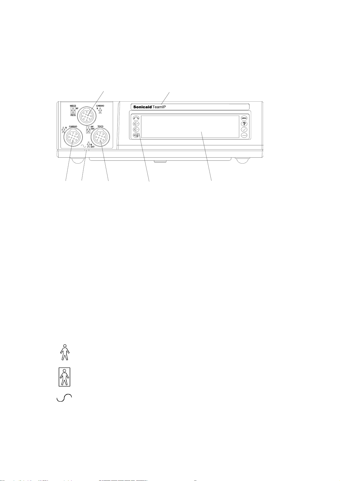
Sonicaid Team Operator’s Manual
1.2 Main unit: front panel
Key
21
76543
1 CARDIO input, blue connector: 2 MHz ultrasound transducer, OR
MECG input: maternal ECG lead (optional)*, OR
FECG input for fetal ECG lead
2 Model identification: Team Standard, Team Duo, Team DM or Team IP
3 CARDIO input, yellow connector: 1.5 MHz ultrasound transducer
4 Power-on indicator light
5 EXT input, pink connector: external contractions (Toco) transducer, OR
INT input: precalibrated IUP catheter-transducer
6 Keypad, with eight control buttons
7 Display panel
* MECG is not available in the USA or Canada.
Explanation of symbols
This symbol, beside the CARDIO and EXT input sockets,
indicates that these connections are classed as Type B.
This symbol, beside the MECG*, FECG and INT TOCO input sockets,
indicates that these connections are classed as Type BF.
This symbol, by the power-on indicator light, denotes AC input.
* MECG is not available in the USA or Canada.
16
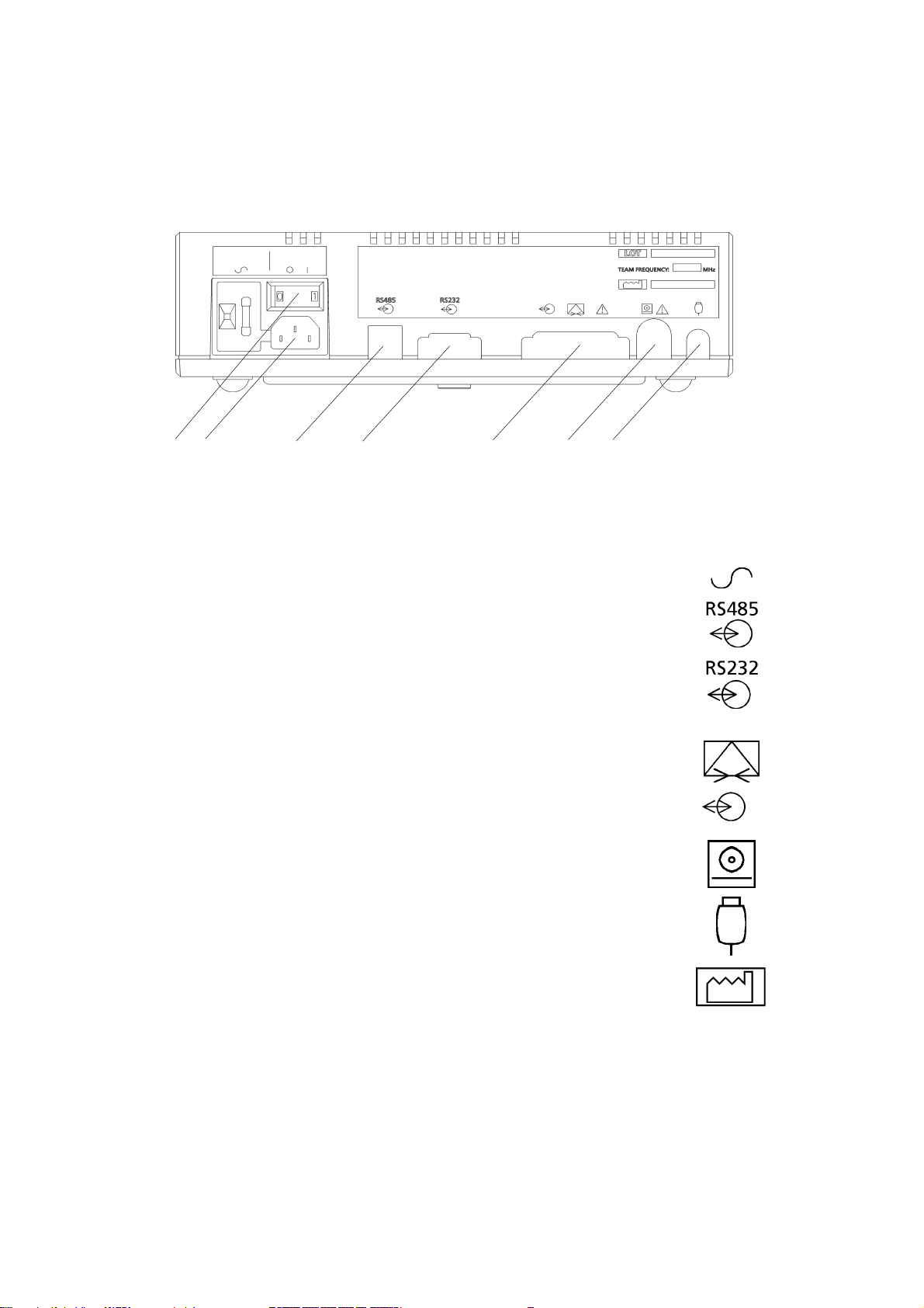
Sonicaid Team Operator’s Manual
1.3 Main unit: rear panel
12 3 4 5 6 7
Key
1 AC mains on/off switch: O = off, 1 = on. When you switch
on, the power on indicator on the front panel shows green.
2 Input socket for the AC mains supply
3* RS485 Interface for Axis.(1.5kV DC isolation).
Pluggable cord connector (PCC-type).*
4* RS232 interface to a PC running Sonicaid FetalCare,
Sonicaid System8002 or a central review system
(500V DC isolation). 9-way D-type connector.*
5* Modem connection for distance monitoring. 25-way D-type.
Connect only modems which comply with EN60950.
Same connector used for the Rimkus Telemetry system.**
6* Team printer connector
8-way DIN-type.*
7* Fetal event marker socket.
1/4″ stereo jack socket.*
O 1
Date of manufacture symbol.
* for details of pin connections, see Appendix 1.
** not available on Teams sold in the USA or Canada.
17
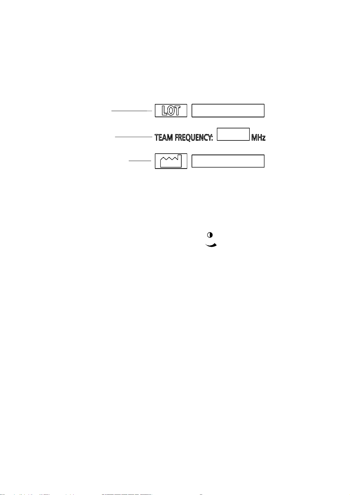
Sonicaid Team Operator’s Manual
Rear panel label
The label on the rear of the Team unit shows the manufacturing serial number, the
Team frequency and the date of manufacture:
Serial number
Team frequency
Date of manufacture
1.4 Contrast control
In the base of the Team main unit is a display
contrast control, marked with this symbol
This control is for the use of service engineers only.
18
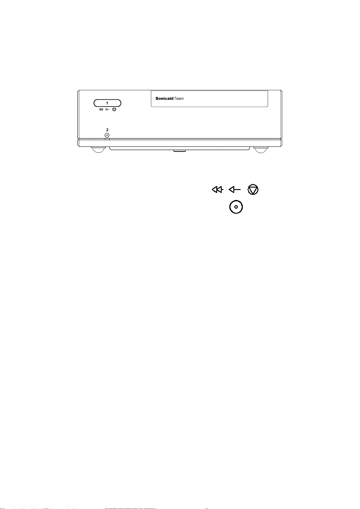
1.5 Team printer: front panel
Key
1 Printer control button. Press once for on-off.
Press and hold down for fast forward.
2 Printer on indicator.
Sonicaid Team Operator’s Manual
19
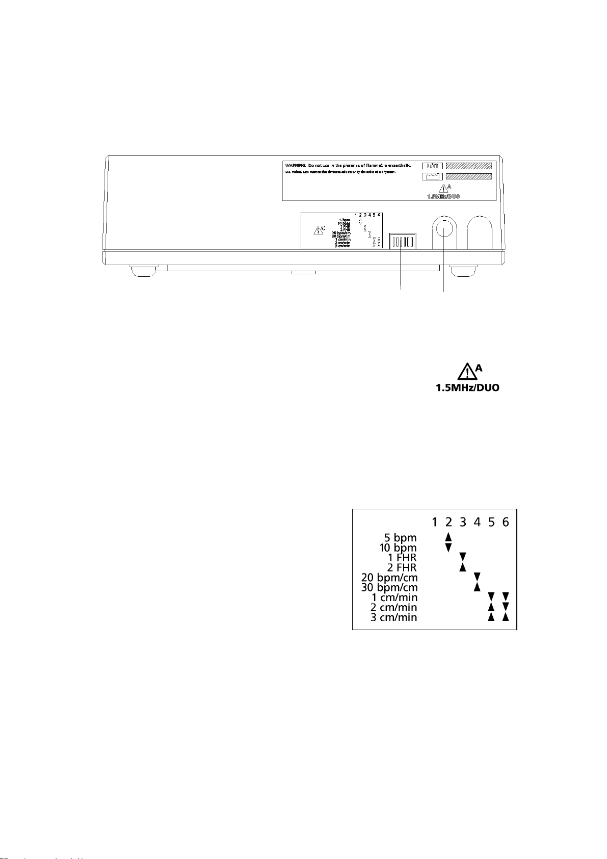
Sonicaid Team Operator’s Manual
1.6 Team printer: rear panel
Key
1 Printer setting switches. See below.
1 2
2
Connector to main unit (7-pin DIN). Connect to the printer
connector on the Team main unit.
Printer switch settings
Paper speed Switch 5 Switch 6
1 cm/min Down Down
2 cm/min Up Down
3 cm/min Up Up
Scale Switch 4
20 bpm/cm Down
30 bpm/cm Up
Dual monitoring Switch 3
Side-by-side Up
Full-width Down
Graticule Switch 2
5 bpm Up
10 bpm Down
Note: switch 1 should always be Up.
Diagram on printer
20

Sonicaid Team Operator’s Manual
1.7 Team printer wedge assembly (option)
For Team fetal monitors there is a wedge which can be fitted between the Team
base unit and the Team printer unit, to improve the visibility of the trace.
To assemble
1 Remove the centre blanking-plug (if fitted) from the Team base unit top.
2 Position the printer wedge on top of the base unit, with the feet of the printer
wedge in the depressions on the rear of the base unit top.
3 Using a screwdriver, secure the screw supplied in centre hole of the wedge top
surface down into the Team base unit with approximately 4 turns.
4 Remove the printer platen. Lift the paper pack for access to the screw-head
beneath.
5 Position the pr inter unit on top of the printer wedge, with the feet of the printer
in the depressions on the printer wedge top.
6 Using a screwdriver, push down and secure the screw with approximately 4 turns.
7 Re-fit the paper pack and plat en.
To disassemble
1 Press the release button beneath the left edge of the printer platen, and lift the
platen to the left and off the top of the printer. Remove the paper pack.
2 Using a screwdriver, release the centre fixing screw (approximately 4 turns).
3 Remove the printer from the printer wedge.
4 Using a screwdriver, release the screw in the centre hole of the wedge top surface
that secures the wedge to the Team base unit.
5 Remove the printer wedge from the Team base unit.
6 Position the pr inter unit on top of the base unit, with the feet of the print er unit
in the depressions on the base unit top.
7 Using a screwdriver, push down and secure the screw with approximately 4 turns.
8 Re-fit the paper pack and plat en.
21
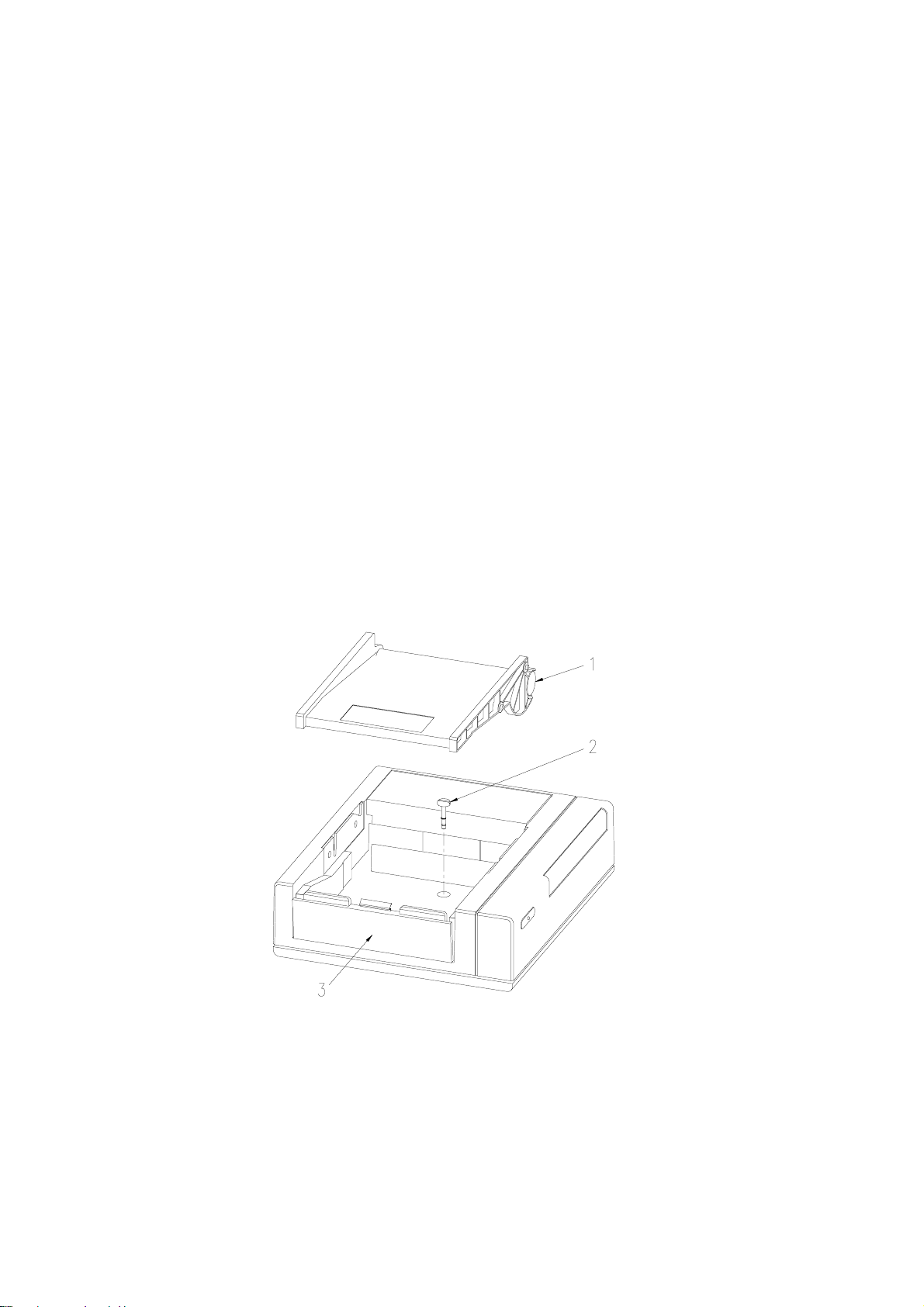
Sonicaid Team Operator’s Manual
1.8 Team printer to Team base unit assembly
The Team base unit is supplied already assembled to the Team printer.
To disassemble
1 Press the release button beneath the left edge of the printer platen.
2 Lift the platen to the left and off the top of the printer.
3 Remove the paper pack.
4 Using a screwdriver, release the centre fixing screw (approximately 4 turns).
5 Remove the printer unit from the main unit.
6 Re-fit the paper pack and plat en.
To reassemble
1 Remove the centre blanking-plug (if fitted) from the Team base unit top.
2 Position the printer unit on top of the base unit. The feet of the printer unit will
locate in depressions on the base unit top.
3 Remove the platen and lift the paper pack for access to the screw-head beneath.
4 Using a screwdriver, push down and secure the screw with approximately 4 turns.
5 Re-fit the paper pack and plat en.
22
1 Printer platen shown removed
2 Centre fixing screw
3 Release button
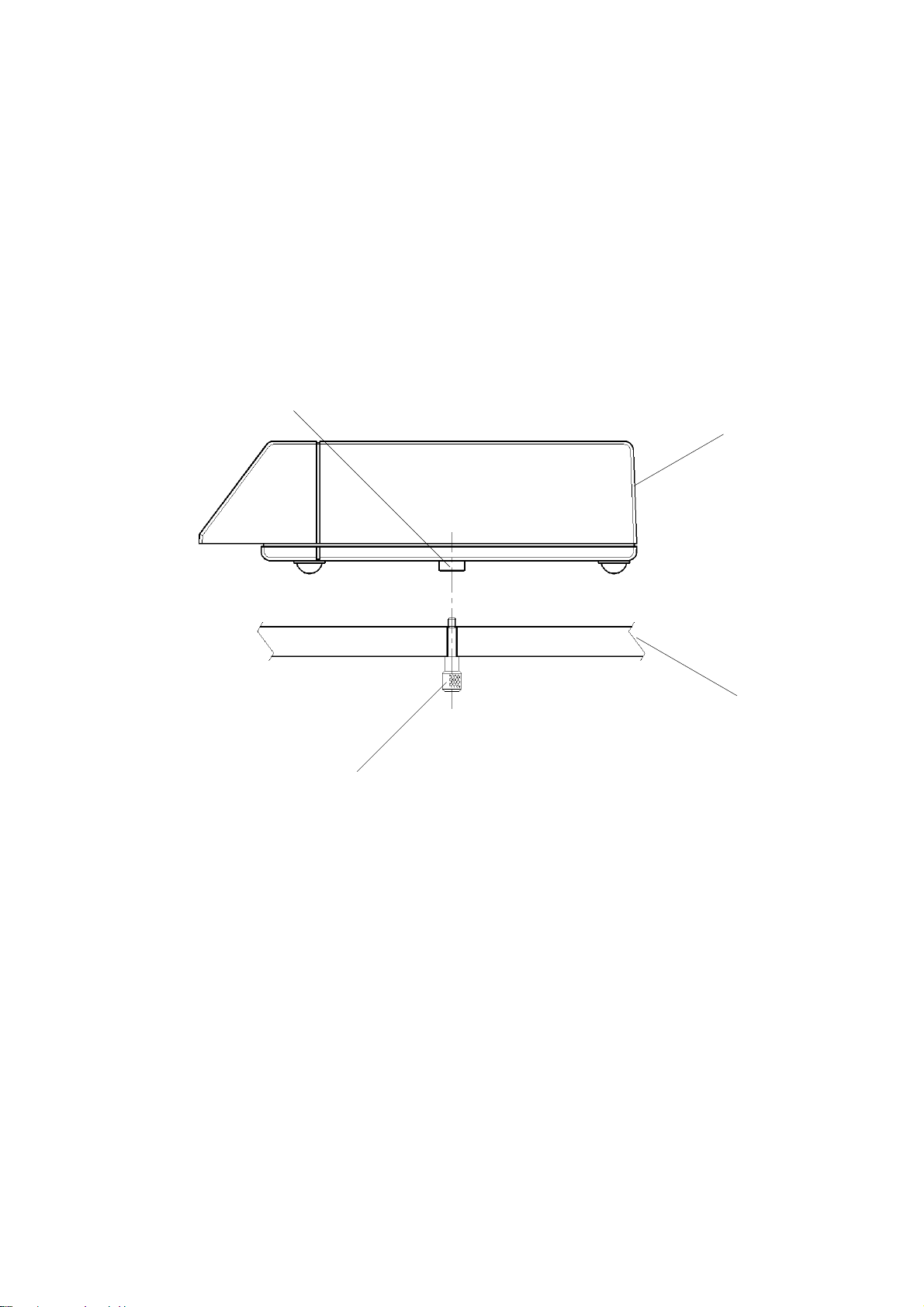
Sonicaid Team Operator’s Manual
1.9 Team base unit to Team trolley assembly
A purpose-designed trolley is an option on Team.
To attach Team to the trolley:
1 Position the Team unit on the trolley top so that the securing screw is in line with
the threaded boss in the centre of the base unit.
2 Reach under the trolley top, and locate the securing screw.
3 Gently push up and secure the screw with three or four turns.
Threaded
Team unit
Securing
Trolley top
23
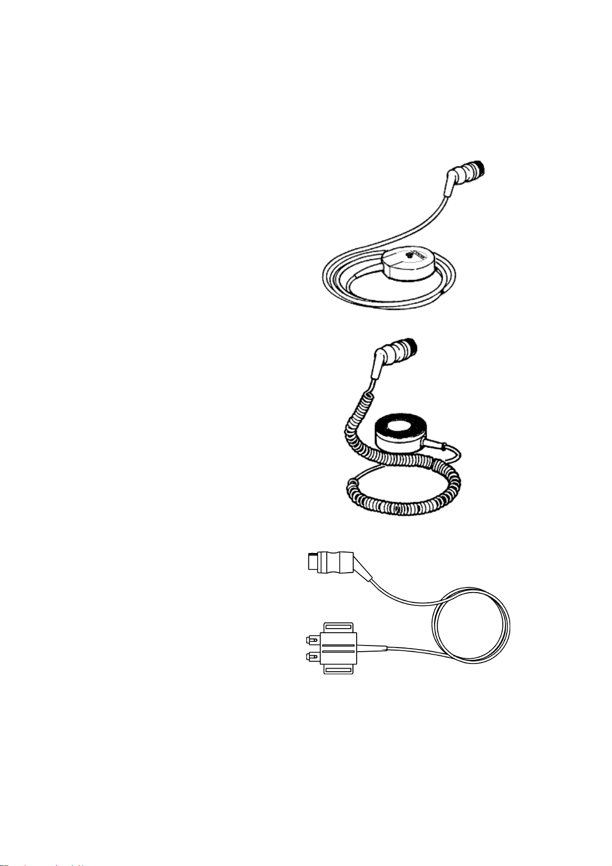
Sonicaid Team Operator’s Manual
1.10 Transducers and cables
Ultrasound transducer
Used for non-invasive monitoring of
the fetal heart rate. Two transducers
are available:
Primary, yellow, 1.5MHz
Secondary, blue, 2.0MHz
The 2.0MHz transducer can only be
used on a Team Duo or Team IP base
unit.
External Toco transducer
Gives a subjective indication of
contractions pressure. Used for
non-invasive monitoring of the
timing, duration and co-ordination
of contractions.
Colour-coded pink, can be used
on all Team base units.
Sonicaid fetal ECG lead*
Strapped to the thigh of the patient,
it is used for interconnection between
Team and a fetal ECG scalp electrode.
Colour-coded blue, can only be used
on a TeamIP base unit.
* The Sonicaid fetal ECG lead is not
available in the USA or Canada.
24

Sonicaid Team Operator’s Manual
Safelinc fetal ECG lead
Attached to the mother’s leg, it is used for interconnection between Team and a
fetal ECG scalp electrode. Colour-coded blue, can only be used on a TeamIP base
unit.
Fetal movement event marker
The patient uses this hand-held pushbutton lead to record fetal movement
events.
It can be used on all Team base units.
Interconnection lead for intraut erine pressure catheter
Used for interconnection between Team and an intrauterine pressure catheter.
Colour-coded pink, can only be used on a Team IP base unit. It is not included with
the unit, but is available as an option.
Maternal ECG lead (option)*
Used for monitoring the maternal heart rate, to check that the heart rate being
recorded belongs to the fetus and not the mother. Colour-coded blue, can only be
used on a Team IP base unit. Not included with the unit, but available as an option.
* The Maternal ECG option is not available in the USA or Canada.
Transducer storage
When not in use, the ultrasound and external toco transducer can be stored by clipping
the stud on the back of the transducer into the rack on the right hand side of the Team
base unit.
25
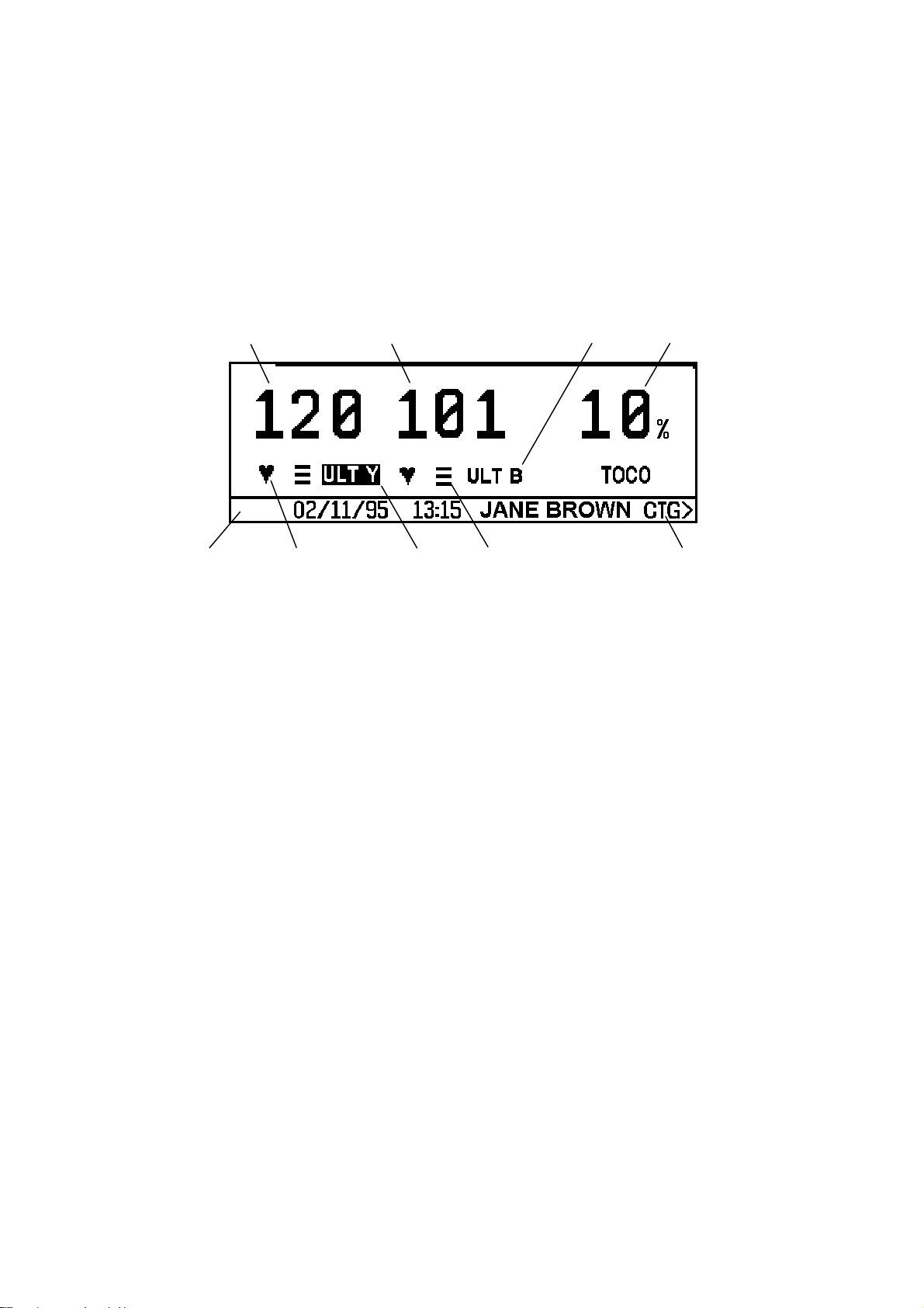
Sonicaid Team Operator’s Manual
1.11 Team display panel
The display panel on the Team base unit has two modes for the display of monitored
information: alphanumeric display and trace display (referred to by Team as CTG).
Alphanumeric display mode
11 23
45 67 8
Key to alphanumeric display
1 Heart rate, in beats per minute.
2 Channel mode, indicates source of monitored information:
ULT-Y 1.5 MHz ultrasound transducer (yellow)
ULT-B 2.0 MHz ultrasound transducer (blue)
FECG Fetal ECG scalp electrode
MECG Maternal ECG electrodes (not available in the USA or Canada)
TOCO External Toco transducer
IUP Intra-uterine pressure catheter
3 Contractions measurement:
Percentage full scale deflection, when using an external Toco transducer.
Pressure, (mmHg/kPa) when using an intrauterine pressure catheter.
4 Display Message Bar: includes date, time and patient name (if entered). Also used
for display of interactive messages.
5 Heart rate lamp: a heart-shaped flashing indicator.
6 The active audio channel: indicated by highlight on channel mode.
7 Signal quality indicator
No bars: no signal
One bar: poor
8 CTG >: press this key to change to Trace Display mode.
Note: this facility is not available on a Team IP when monitoring two heart rates
using either ULT-Y and FECG or ULT-Y and MECG.
Two bars: average
Three bars: good
26
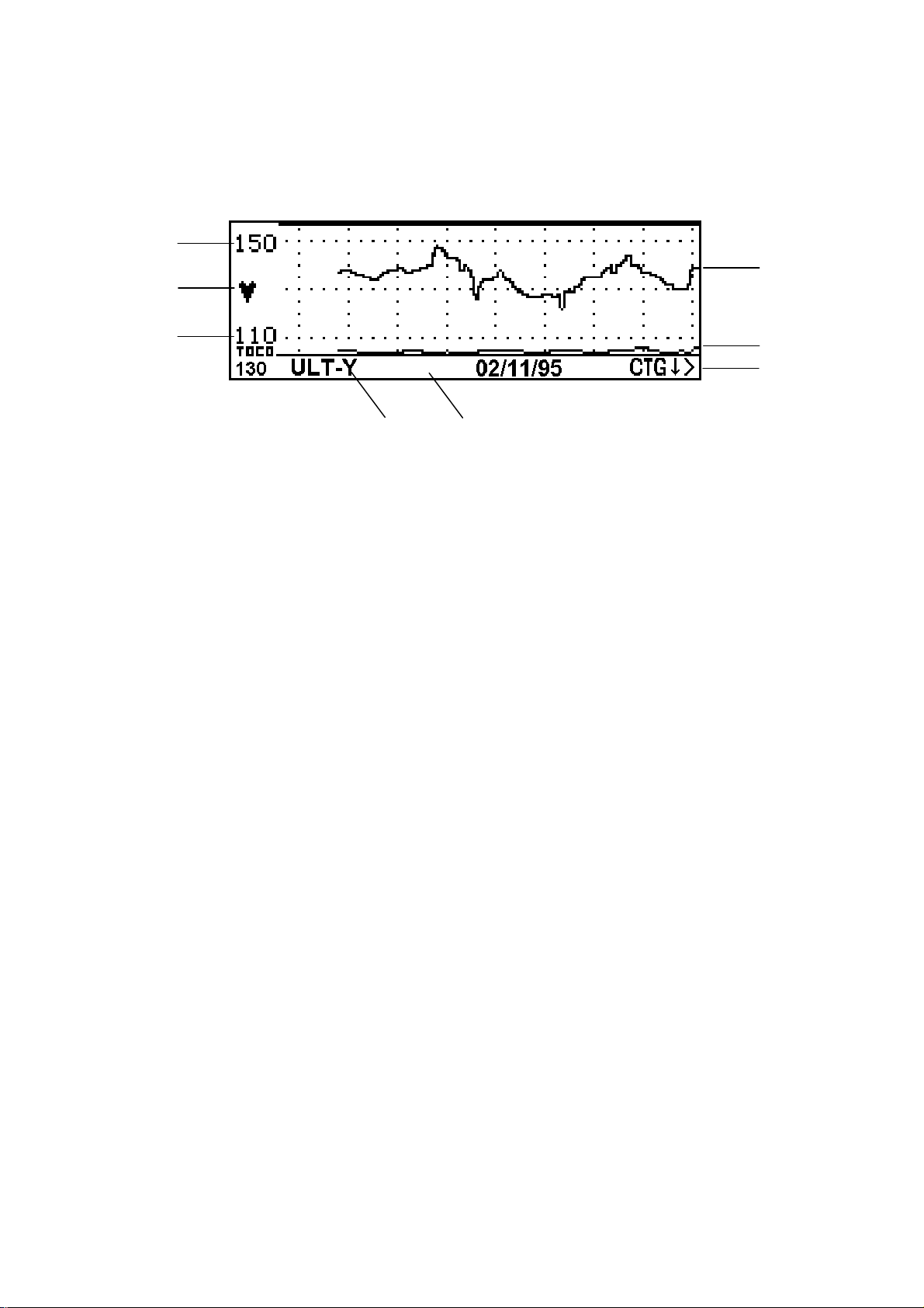
Sonicaid Team Operator’s Manual
FHR Trace Display mode (CTG mode)
1
2
1
34
1 Heart rate range (beats per minute): indicates the range currently displayed.
2 Heart rate lamp: heart-shaped flashing indicator.
3 Channel mode: indicates heart rate channel on display.
4 Display message bar, used for display of interactive messages.
5
6
7
5 Heart rate trace:
Displays the active audio channel (or channel 1, yellow, if no audio is selected).
If monitoring twin heart rates, only one channel can be displayed at a time.
6 Contractions trace, compressed.
7CTG ↓ >: this menu pointer changes title and function. See below, Scr olling the
trace and returning to the alphanumeric display below.
Scrolling the trace and returning to the alphanumeric display
The fetal heart rate trace is initially displayed over the range 110-150bpm. The menu
pointer in the display message bar reads [CTG
È >].
To scroll the display vertically:
1 Press the Enter button next to the menu pointer.
The display will show the trace over the range 80-120bpm.
The menu pointer will then read [CTG
Ç >].
2 Press the Enter button next to the menu pointer.
The display will show the trace over the range 140-180bpm.
The menu pointer will then read [ALPHA >].
3 Press the Enter button next to the menu pointer.
The display will return to Alphanumeric display mode.
To scroll the display horizontically, press the Clinical Event marker button [9].
27

Sonicaid Team Operator’s Manual
1.12 The Team Keypad
1
2
3
4
There are eight buttons on the Team display panel. Their primary functions are:
1 Toco zero: zeroes the external Toco (contractions) transducer or IUP catheter.
2 Volume control up
3 Volume control down
4 Channel select
5 Menu access
6 Display Help page
7 Clinical event marker
8 Enter: confirms an entry or switches display modes
5
6
7
8
28

Sonicaid Team Operator’s Manual
2 Getting Started
2.1 Summary of recording procedure
Setup
1 Place transducer belts across the bed or chair.
2 Make the patient comfortable in a semi-recumbent or sitting position.
Preparing the Team
1 Switch on. The on/off sw itch is on the rear of the base unit.
2 Check paper. Is there sufficient paper for the monitoring session? Make sure the
printer platen is securely closed.
3 Connect transducers. The plugs and sockets are colour-coded; the display confirms
transducer connection.
Transducer placement
1 Palpate the abdomen to determine fetal lie and position.
2 Position the Toco t ransducer (pink) centrally, halfway between fundus and
umbilicus. Do not use gel. Secure with belt and buckle.
3 Zero the Toco. Make sure the uterus is relaxed, then press the Toco zero button.
The 10% baseline is displayed.
4 Gel the ultrasound transducer (yellow). Place it on the abdomen so as to obtain a
clear heart sound. Secure with belt and buckle.
5 Check that the fetal heart rate is clear, and distinct from the maternal pulse rate
taken at the mother’s wrist. Note the maternal pulse rate on the chart paper.
Optimum signal quality for the fetal heart rate is shown by 3 bars on the display,
with a flashing heart at each beat.
6 Adjust t he volume using the volume up and down keys.
7 Connect the fetal event marker to the socket on the rear panel. Show the patient
how to use it.
29

Sonicaid Team Operator’s Manual
Using the printer
1 To swit ch the printer on, press the button on the printer front panel.
2 To fas t forward the paper, press and hold down the printer button.
3 To stop the printer, press the printer button again.
Using the second ultrasound tr ansducer for twins
1 Connect the second ultrasound transducer (blue) to the Team. The display
switches to twin heart rate display.
2 Place both ultrasound transducers on the patient’s abdomen in the optimum
position. Use the blue ultrasound transducer to monitor the first, presenting twin.
3 Make sure each fetal heart rate is from a separate fetus. See Section 3.4. If in doubt,
ask for assistance. Secure the ultrasound transducers with belts and buckles.
4 To select Audio, press the bottom left button on the keypad. The active audio
channel is highlighted on the display.
Monitoring fetal ECG
Using a Sonicaid scalp electrode:
1 Put electrode gel on the base of the leg plate, then strap the leg plate to the
patient’s thigh. Secure with the belt.
2 Connect the FECG lead to the Team.
3 Once the membranes are ruptured, attach the electrode to the fetus as described
in the electrode instructions.
4 Connect the electrode leads to the leg plate. Make sure a good signal is
maintained.
5 Wait for the signal to stabilize and a clear fetal heart rate to be displayed on the
Team base unit display. Then adjust the volume control.
Using a Safelinc electrode:
1 Attach the FECG lead to the mother’s leg.
2 Once the membranes are ruptured, attach the FECG electrode to the fetal pre-
senting part.
3 Connext the FECG electrode to the FECG lead.
4 Wait for the signal to stabilize and a clear fetal heart rate to be displayed on the
Team base unit display. Then adjust the volume control.
See also Section 3.3.
30

Sonicaid Team Operator’s Manual
2.2 The Team printer
There are three Team printers available:
Standard Thermal printer for a continuous paper record of monit ored data.
Care * With analysis for use during the antepartum period. The analysis
measures fetal heart rate parameters, performs a test against criteria
that define a normal record, and highlights any abnormalities.
Trend * With analysis for use during the intrapartum period. The analysis
measures fetal heart rate parameters at regular intervals, identifying
suspicious fetal heart rate trends.
* Sonicaid Trend is not available for sale in the USA and Canada.
The procedures described here on trace annotation, loading printer paper and printer
operation apply to all three types of printer. See Chapter 6 Care Printe r and Chapter 7
Trend Printer for specific information on these two types.
Paper
The printer uses a plain, thermal paper pack (part number 8400-8003). Use only
Sonicaid paper. The use of non-approved paper may result in poor quality
printing or damage to the printer, and could invalidate the printer warranty.
Horizontal scale (print speed)
The printer has three speeds: 1 cm/min, 2 cm/min and 3 cm/min. The following table
shows the default print speed in different countries:
1 cm/min 3 cm/min
North America (USA and Canada) 9
Europe and the rest of the world 9
To change the print speed, see section 2.5.
31

Sonicaid Team Operator’s Manual
Vertical scale
The printer’s vertical scale can be 20 bpm/cm or 30 bpm/cm. The following table
shows the default scale in different countries:
20 bpm/cm 30 bpm/cm
North America (USA and Canada) 9
Europe and the rest of the world 9
To change the vertical scale, see section 2.3.
2.3 Trace annotation
Trace header
When the printer is switched on, a header is printed before the trace data and graticule. The header includes user name, date and time, and patient details (if entered).
Graticule
The graticule is printed at the same time as the trace data, with a 5 bpm or 10 bpm
grid. Set printer switch 2 up for 5 bpm, down for 10 bpm.
Fetal heart rate scale
Set printer switch 4 down for 20 bpm/cm (range 50–210 bpm), or up for 30 bpm/cm
(range 30–240 bpm).
32

Sonicaid Team Operator’s Manual
Twin fetal heart rates
Set switch 3 down to print twin fetal heart rate traces superimposed on a full-width
fetal heart rate scale, or up to print side-by-side on two separate fetal heart rate
scales.
In side-by-side printing, the primary channel (ULT-Y) is printed on t he top scale, the
secondary channel (ULT-B or FECG or MECG*) below. The FHR range depends on the
scale setting:
20 bpm/cm 30 bpm/cm
100–180 bpm 60–180 bpm
In full-width printing, the primary channel (ULT-Y) is printed as a solid line, the
secondary channel (ULT-B or FECG or MECG*) as a dotted line.
* MECG is not available in the USA and Canada.
Contractions scales
When using an external Toco transducer, the contractions scale is 0–100%, relative
units. When using an intrauterine pressure catheter, the contractions scale is 0–100
mmHg or 0–15 kPa, depending on the units of measure selected.
Trace annotation
The printer automatically annotates the trace with the following informat ion:
z Heart rate scale
z Contractions scale
z Monitoring mode
z Date and time
z Paper speed
z Signal loss %
Annotation occurs when the printer is switched on, and then at 10-minute intervals (at
1 cm/min) or 5-minute intervals (at 2 or 3 cm/min). Each hour is divided into 5-minute
or 10-minute segments starting on the hour, s o the second annotation may not print
for up to 19 minutes.
Signal loss is expressed as a percentage over the period between annotat ions.
33
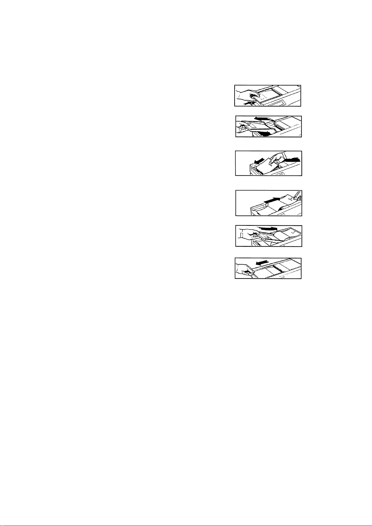
Sonicaid Team Operator’s Manual
2.4 Loading printer paper
1 Press the release-button beneath the left edge of
the printer platen.
2 Lift the platen to the left and off the top of the
printer.
3 Place the pack of paper in the compartment
beneath. (The top side of a new pack of paper is
identified by the message ‘LOAD PACK’, and an
arrow pointing to the right. For a partly-used pack,
align the blue marks on the pack with the blue
marks on the compartment.)
4 Pull two folds clear of the chart printer, to the right.
5 Then fold them back to the left, across the top of
the platen, as it is fitted at a downwards angle to
the right.
6 If necessary, adjust the paper positioning between
the sides of the paper channel and press down on
the left edge of the platento latch it.
If, after a period of use, the print quality is poor, check
that the platen is closed. If still poor, clean the print
head as detailed in the Technical Maintenance section.
34
 Loading…