
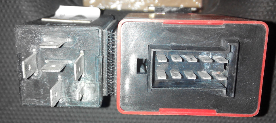
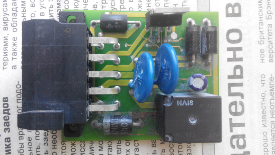
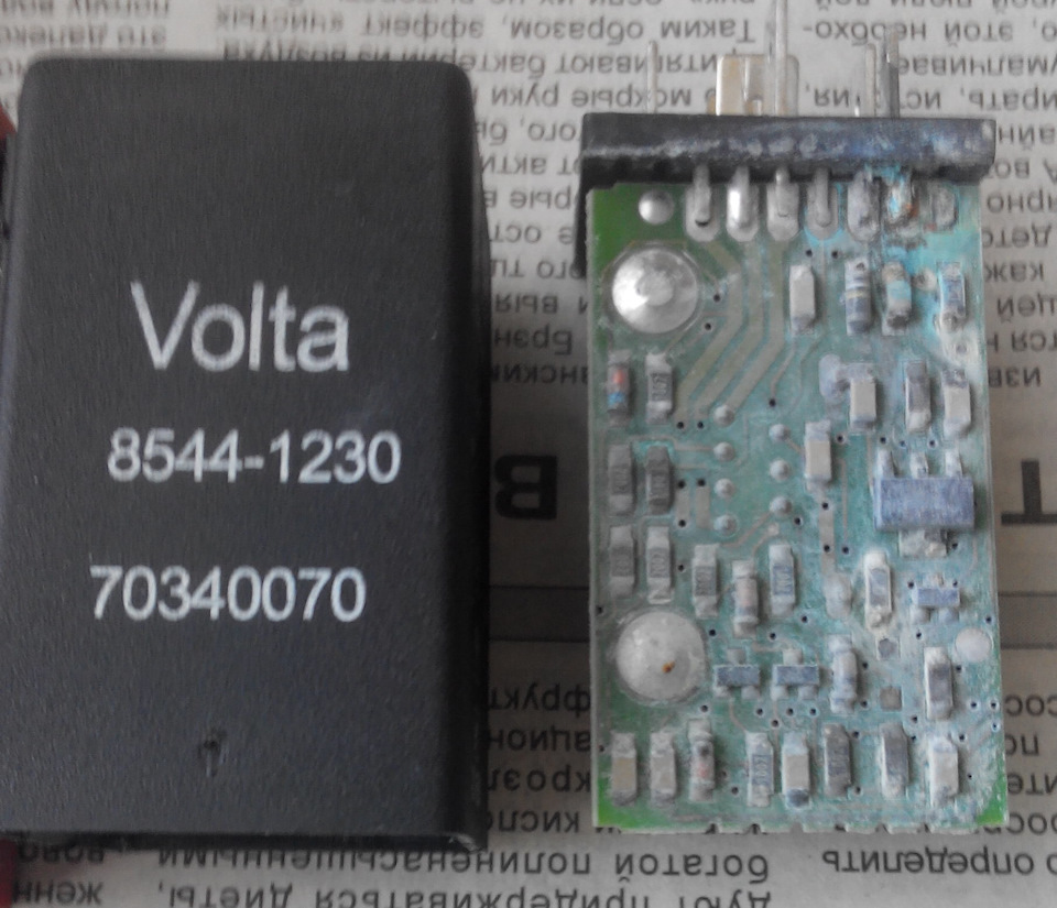
После приобретения вело багажника на фаркоп, появилась потребность в использовании розетки автомобиля. В комплектации автомобиля установлена штатная 13-pinовая розетка, а на вело багажнике — 7-pinовая. Взвесив все за и против, основной аргумент был — цена, было принято решение о замене 13-pinовой розетки автомобиля на 7-pinовую. С самой установкой розетки проблемы были минимальные, а вот с подключением — возникли небольшие затруднения: не работает МодульVOLTA SIK5.0 12V 8545-1214 — сигналы приходят, . а из модуля не выходят.
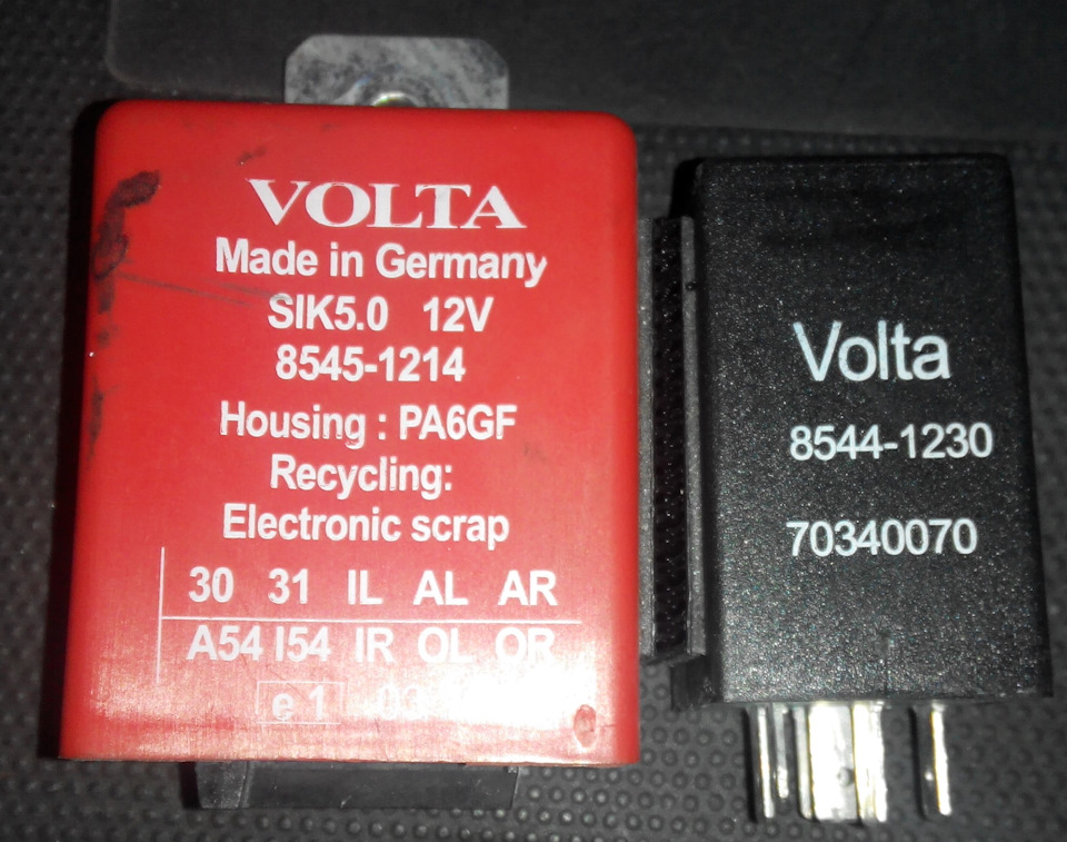
Модуль помогает машине определять наличие прицепа как для отключения задних парктроников при движении задним ходом, так и для системы стабилизации автомобиля при буксировке прицепа (TSA).
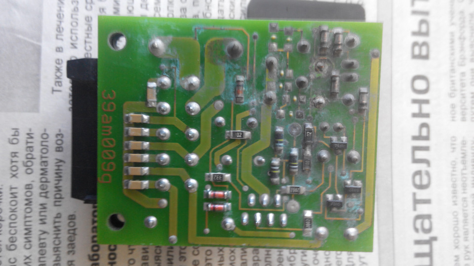
Причина неисправности — окисление, и как следствие перегнивание дорожек электрической платы из-за конденсата.
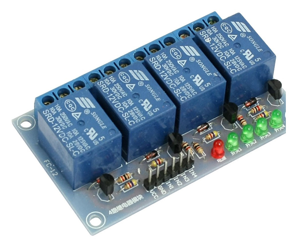
Заказал из Китая блок реле 12В 10А.
А пока блок в пути, собрал все по временной схеме на автомобильных релюшках.
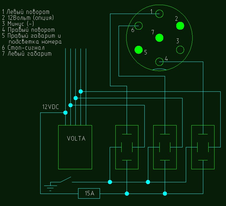
В качестве переключателя использовал АЗС-15 на 15А. Переключатель устанавливал по рекомендациям форума для, якобы исключения щелкания релюшек. Из своего опыта — как с выключенным, так и с включенным переключателем все равно слышно щелкание релюшек.
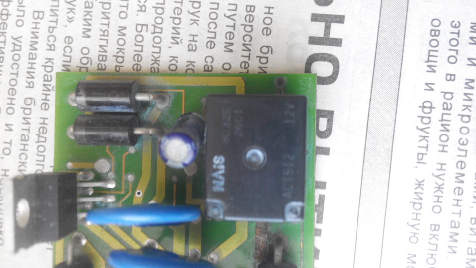
Если у кого-нибудь есть схема или фото внутренностей рабочего Модуля VOLTA SIK5.0 12V 8545-1214 поделитесь!
What is DIT8545?
This is Ceratrans Driver. |
[PDF] Complete Technical Details can be found in the DIT8545 datasheet provided at this page.
Datasheet Summary in PDF Filewww datasheetgo.com DIT8545 Ceratrans Driver for LCD Backlight DESCRIPTIONS DIT8545 is an advanced LCD backlight inverter control IC based on the piezo ceramic transformer The new control scheme employing the variable fr equency and duty control achieves the very high efficiency over 90 In this control scheme the soft start and zero voltage switching functions are aut omatically obtained DIT8545 can realize the CCFL backlight inverter with small size and low cost FEATURES Soft start function Programmable Operating Frequency Analog Dimming Control Function Burst Dimming Control ON OFF Control Function Open Lamp Protection 10SSOP Package ORDER INFORMATION Device DIT8545 Package 10SSOP 225 Operating Temp 25 OC 85 OC BLOCK DIAGRAM CT VCC UVLO 1 RT CT RT 10 OUT 2 EI VFVCO Driver 9 GND TONCT L 3 Error Amp 8 Bandgap Reference Bias Generator Latch EO ON OFF 4 TONCTL 7 PROT 5 6 Aug 2002 WWW INTERPIONSEMI COM 1 www datasheetgo.com DIT8545 Ceratrans Driver for LCD Backlight PIN CONNECTIONS VCC 10 OUT 9 GND 8 ON OFF 7 PROT 6 DIT8545 1 CT 2 RT 3 EI 4 EO 5 TONCTL PIN DESCRIPTIONS NO 1 2 3 4 5 6 7 8 9 10 SYMBOL CT RT EI EO TONCTL PROT ON OFF GND OUT VCC I O I I I O I I I O DESCRIPTION TIMING CAPACITOR CONNECTION TI |
Datasheet Download (PDF)
| Related Part Number
Although each manufacturer has the same part name, the detailed parameters of its function may differ slightly. Therefore, it is important to check accurate data from various manufacturers.
Sony CXP85452 Microcomputer
CMOS 8-bit Single Chip Microcomputer
Preview
[ Sony Corporation ]
Ti LP8545 Led
LP8545 High-Efficiency LED Backlight Driver for Notebooks (Rev. D)
Preview
[ Texas Instruments ]
Dynex MDFB8545 Diode
Fast Recovery Diode
Preview
[ Dynex ]
Electronic Components Distributor
DataSheetGo.com offers a broad range of information on various semiconductors, including their specifications, features, applications, and pricing, among others.
With the rapid development and evolution of semiconductor technology, it is essential to have an accurate and reliable source of information. DataSheetGo.com ensures that its users have access to the most up-to-date information available.
This site is user-friendly, with an easy-to-use interface that allows users to navigate seamlessly through the site. Its search function is powerful, enabling users to find the specific information they need quickly and easily.
Related keywords to DIT8545 include schematic, equivalent, circuit, and replacement
Table of Contents
Introduction
Michel asked me to design an analog LED controller with 5 channels, since he wanted to be able to control a nice LED strip with an RGB LED and a warm white and cool white LED (Like Philips Hue). When searching the internet he could only find controllers with a single channel, four channels or ten channels. But a 5 channel controller for these kind of LED strips was simply not available!
He was very specific in his request, so I wrote down some design parameters first.
Also check out our YouTube video, subscribe, hit the bell and send the link to all your friends. You know the drill 😉
ET-AL01 — 5 Channel Analog LED Controller
Please subscribe to our YouTube channel and hit the bell to never miss a (esp)thing!
Design parameters
The requirements were:
- ESP32 or ESP8266 controlled. Preferably ESP32, due to the higher PWM frequencies the ESP32 supports
- Operating at 12 or 24V DC, so the LED power supply could also feed the controller
- Five channels, with an as high as possible current capability
- Must fit in a nice looking enclosure, should not look too industrial
- Parts should be available at AliExpress at affordable prices, making it as cheap as possible to build
- Firmware should be ESPhome. (Something which is achieved by using the ESP32 / ESP8266 modules)
Practical design
The heart of the design is a “Wemos Mini” (compatible) module. By using these modules, it becomes very easy to integrate, and greatly simplifies the design. It also allows people to pick an ESP32 or ESP8266 module, which creates a little bit of flexibility too.
To control the output channels, MOSFETs will be used, with a standard footprint / case so that a number of compatible models can be applied. The design is flexible enough to drive most of them.
Why use a 74HCT244 chip?
Since the ESP modules use I/O levels of 3.3V, and a lot of MOSFETs require more control voltage, a so-called “level shifter” needs to be used. Many different solutions exist, ranging from the usage of driving transistors, special level shift chips, or the usage of TTL chips. All solutions have pros and cons, and the decision has been made to use a TTL chip in this design. The decision was based on the easy (cheap) availability on AliExpress, very standardized operating parameters (irrespective of manufacturers!) and small footprint on the PCB.
The 74244 exists in a number of TTL families, all with their own parameters. When looking at the requirements of the design of the controller, the most suitable family is the “HCT” family. See the below table from the datasheet of Texas Instruments SN74HCT244:
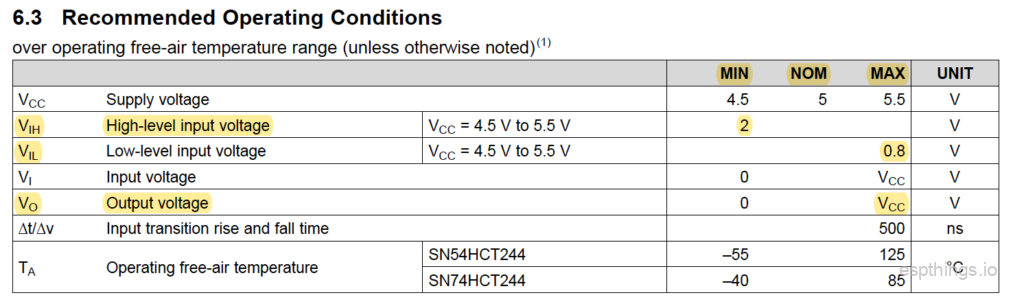
See the below table for the IO levels of the ESP32:

If you compare the two tables you see that the output level of the ESP chips are defined as a factor of “VDD”. VDD is for the modules used 3.3V, so if we convert the levels listed to fixed numbers, we see that the “High-level output voltage” has a minimum of 2.64V, and for the “Low-level output voltage” a maximum of 0.33V.
When the input levels of the 74HCT244 datasheet are checked, we see that the max. “Low-level input voltage” is defined as 0.8V. Therefore the 0.33V is low enough to ensure that the level is detected properly. Same for the min. “High-level input voltage” which is defined as 2V. The 2.64V from the ESP32 is therefore more than enough to ensure the logic “1” is detected properly.
In the table you can also see the output voltage specification. There are only two levels given, “Min” and “Max”. The “Nom” (nominal) is missing, since the output will only take 2 possible levels, which are defined as 0V and “Vcc”. The “Vcc” in the circuit will be 5V, therefore the output voltage for a logical “1” will be 5V. This is very beneficial for the driving of the MOSFET connected to the output pin.
The last parameter which is important is the max. output current per pin:

The 74HCT244 can supply max. 35mA continuously per pin. This is important to drive the gate of the MOSFET sufficiently in a rapid manner. The gate – source connection of a MOSFET acts like a capacitor, which needs to be charged for the resistance between the drain and source to lower. If the current flowing into the gate is limited / low, this charging will be slow(er). The HCT series has one of the highest maximum output currents. The opposite for the “switching off” of the MOSFET, the capacitor needs to be discharged. A lower discharge current capability will result in slower switching.
For a more in-depth discussion regarding the design, read this blog post.
Circuit diagram and PCB
The design I came up with is this:
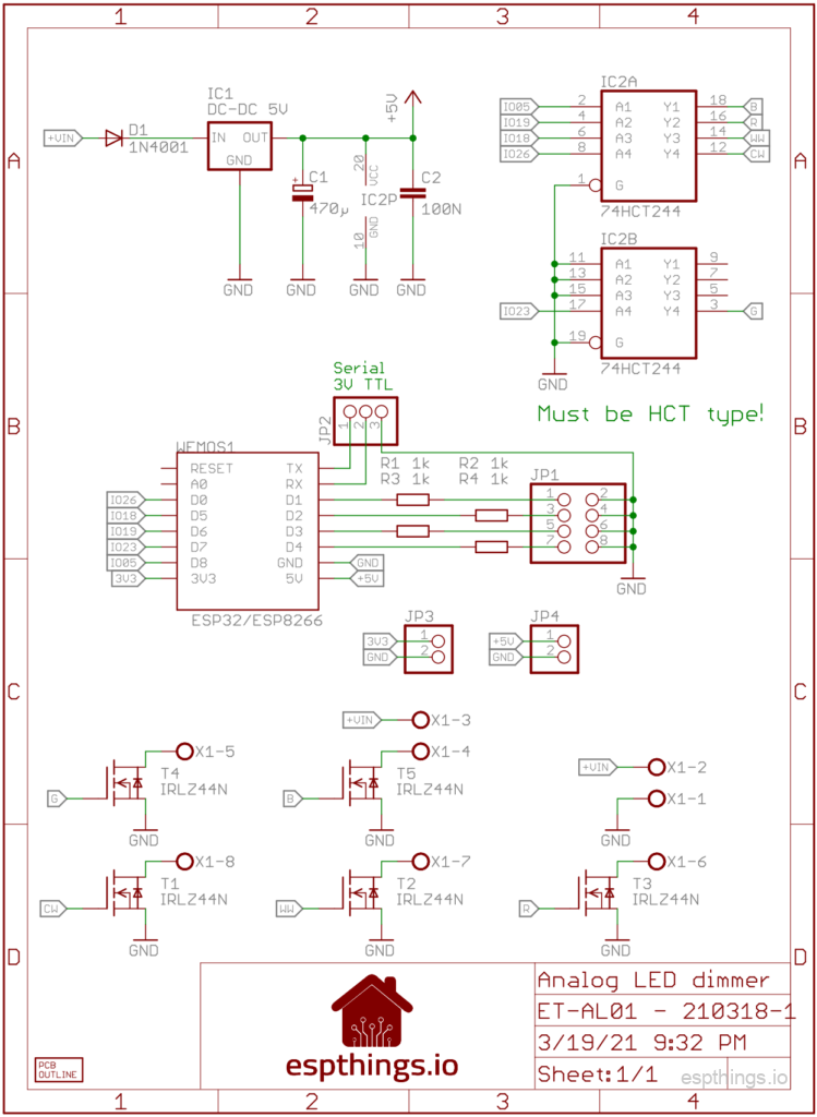
The PCB design of this diagram:

On top you see the GPIO interface pins. These can be used as a general purpose IOs. The number between ( ) are the IO numbers of the ESP32 modules, and the numbers between the [ ] are the IO numbers of the ESP8266 modules. You will need these numbers to configure the IOs in the software configuration. These pins are capable of handling 3.3V and 5V input levels, and if used as an output, 3.3V output level. To feed possible sensors, right next to the GPIO pins you will see the 5V and 3.3V power output connections. The 3.3V power is coming from the ESP module, and is limited in power. Try to limit the amount of current drawn from the pin (Think in currents not exceeding about 100mA). If you need a lot more current at 3.3V level, use an external voltage regulator, connected to the 5V power output. This is fed by the regulator on the PCB, and would normally be able to supply 250mA or more, depending on the regulator used, to the pin.
Next to the GPIO pins, the serial port of the ESP module has been made available. This serial port uses 3.3V signal levels. “TXo” means transmit out, data from the ESP module to the outside world, “RXi” means receive data from the outside world to the ESP module. Be careful not to exceed the 3.3V voltage levels, since this might damage the module permanently.
At the bottom you see the screw terminals. The power input is located on the right hand side, and the LED strip will be connected to “CW, WW, R, G, B, +”
Build it!
Bill Of Materials
See below the list with the components you will need to build the AL01 controller. A number of these items will not be sold in smaller quantities at AliExpress. We will try to use the same components as much as possible in future projects.
We would really appreciate it if you will use the links below to buy the components, since it will give a little bit of commission to us without any additional cost for yourself. These commissions will be used to cover some of the costs involved in the development of the project design.
| Reference | Qty | Description | Link |
| WEMOS1 | 1 | Wemos Mini D1 ESP32* | AliExpress |
| WEMOS1 | Wemos Mini D1 ESP8266* | AliExpress | |
| IC1 | 1 | Switching regulator 8-32V in, 5V out | AliExpress |
| IC2 | 1 | 74HCT244 | AliExpress |
| T1, T2, T3, T4, T5 | 5 | IRLZ44N or compatible logic level MOSFET | AliExpress |
| D1 | 1 | 1N4001 | AliExpress |
| C1 | 1 | 470µF / 16V 6mm diameter, 2.54mm pitch | AliExpress |
| C2 | 1 | 0.1µF – pitch 5.08mm | AliExpress |
| R1, R2, R3, R4 | 4 | Resistor 1k | AliExpress |
| X1 | 1 | 8 pole terminal, or 4x 2 pole. 5.00mm pitch | AliExpress |
| JP1, JP2, JP3 | Male pin headers. 2.54mm pitch | AliExpress | |
| Enclosure | 1 | 76x56x29mm (AK-N-04) | AliExpress |
| PCB | 1 | A 5-pack is the smallest order at PCBway, so talk to your friends 😉 | PCBway |
| LED strip | opt. | 12v RGBCCT | AliExpress |
| LED strip | opt. | 24v RGBCCT | AliExpress |
| Power Supply | opt. | SANPU SMPS LED Driver 110v/220v 12v 150w | AliExpress |
| Power Supply | opt. | SANPU SMPS LED Driver 110v/220v 24v 150w | AliExpress |
* You only require one of the modules!
Putting it together
When building the project it is the easiest to start with identifying the components purchased as discussed in the blog post. After sorting the components and cleaning the PCB, start with the lowest components first. For this project, we advise to work in this order:
- Resistors
- Diode
- 74HCT244
- Pin headers
- Screw terminals
- ESP module headers (Use the hints in the soldering blog post!)
- Electrolytic capacitor
- MOSFETs
- Voltage regulator. Make sure that the voltage regulator is not taller than the MOSFETs! You can do this by bending the pins of the voltage regulator a little bit, so it will lean a little bit.
Once all components are soldered in place, perform a good visual check of all joints, and pay particular attention to possible solder bridges (unwanted solder connections between pins). Clean the excess solder flux from the PCB using alcohol!
Software configuration
Once everything is soldered together, it is time for the software configuration. Follow the instructions in our YouTube video. Configuration files below:
Secrets:
esphome_wifi_ssid: 'your_ssid'
esphome_wifi_password: 'your_wifi_password'
esphome_ap_password: 'your_ap_password'
esphome_api_password: 'your_api_password'
esphome_ota_password: 'your_ota_password'
ESP32:
substitutions:
  devicename: et-al01_esp32
  long_devicename: ET-Al01 Analog LED controller (ESP32)

esphome:
  name: $devicename
  platform: ESP32
  board: mhetesp32minikit

wifi:
  ssid: !secret esphome_wifi_ssid
  password: !secret esphome_wifi_password
  ap:
    ssid: "$devicename Fallback Hotspot"
    password: !secret esphome_ap_password

captive_portal:

logger:

api:
  password: !secret esphome_api_password

ota:
  password: !secret esphome_ota_password

sensor:
  - platform: wifi_signal
    name: "WiFi Signal $devicename"
    update_interval: 60s

output:
  - platform: ledc
    pin: 26
    frequency: 25000Hz
    id: ledc_cw
  - platform: ledc
    pin: 18
    frequency: 25000Hz
    id: ledc_ww
  - platform: ledc
    pin: 19
    frequency: 25000Hz
    id: ledc_r
  - platform: ledc
    pin: 23
    frequency: 25000Hz
    id: ledc_g
  - platform: ledc
    pin: 05
    frequency: 25000Hz
    id: ledc_b

light:
  - platform: rgbww
    name: "$long_devicename LED-strip"
    warm_white: ledc_ww
    cold_white: ledc_cw
    red: ledc_r
    green: ledc_g
    blue: ledc_b
    cold_white_color_temperature: 5000K
    warm_white_color_temperature: 3000K
ESP8266:
substitutions:
  devicename: et-al01_esp8266
  long_devicename: ET-Al01 Analog LED controller (ESP8266)

esphome:
  name: $devicename
  platform: ESP8266
  board: d1_mini

wifi:
  ssid: !secret esphome_wifi_ssid
  password: !secret esphome_wifi_password
  ap:
    ssid: "$devicename Fallback Hotspot"
    password: !secret esphome_ap_password

captive_portal:

logger:

api:
  password: !secret esphome_api_password

ota:
  password: !secret esphome_ota_password

sensor:
  - platform: wifi_signal
    name: "WiFi Signal $devicename"
    update_interval: 60s

output:
  - platform: esp8266_pwm
    pin: D0
    frequency: 100 Hz
    id: ledc_cw
  - platform: esp8266_pwm
    pin: D5
    frequency: 100 Hz
    id: ledc_ww
  - platform: esp8266_pwm
    pin: D6
    frequency: 100 Hz
    id: ledc_r
  - platform: esp8266_pwm
    pin: D7
    frequency: 100 Hz
    id: ledc_g
  - platform: esp8266_pwm
    pin: D8
    frequency: 100 Hz
    id: ledc_b

light:
  - platform: rgbww
    name: "$long_devicename LED-strip"
    warm_white: ledc_ww
    cold_white: ledc_cw
    red: ledc_r
    green: ledc_g
    blue: ledc_b
    cold_white_color_temperature: 5000K
    warm_white_color_temperature: 3000K
Using a channel as a digital output
If you do not require all the analog channels, there is an easy option to create a digital channel out of an unused analog channel. To do this, do not mount the MOSFET for the channel, but instead install a jumper from the top connection to the center connection of the MOSFET footprint. This will make a direct connection from the 74HCT244 output, to the screw terminal. Once this connection is made, the output can be used to drive a WS28XX (or compatible) LED strip. For the respective channel a YAML entry needs to be edited;
Light:
  - platform: fastled_clockless
    chipset: ws2811
    pin: GPIO5
    num_leds: 238
    max_refresh_rate: 8ms
    rgb_order: BRG
    name: "$long_devicename-DIGITAL"
    effects:
      - addressable_rainbow:
          name: Rainbow Effect With Custom Values
          speed: 10
          width: 50
      - addressable_rainbow:
          name: Rainbow mega fast
          speed: 35
          width: 200
      - addressable_scan:
          name: Scan Effect With Custom Values
          move_interval: 100ms
          scan_width: 1
      - addressable_color_wipe:
          name: Color Wipe Effect With Custom Values
          colors:
            - red: 100%
              green: 100%
              blue: 100%
              num_leds: 1
            - red: 0%
              green: 0%
              blue: 0%
              num_leds: 1
          add_led_interval: 100ms
          reverse: False
Final thoughts
After the design was finished, we both build a controller to test. The controller which Michel built has been in use for a number of weeks now, without any issue. No issues with MOSFETs getting warm or overheating, no issues with stability, so we are confident that this controller will work for you too.
This project, the ET-AL01 5 channel Analog LED controller, was the reason for starting this website. We found out that there are more circuits which we think people are looking for to build. What we decided to do is to create more projects with the same design philosophy; Easy to build, of easily and cheaply available components, and well tested. And they need to look nice too!
For us one of the major things is also to make sure that the projects / circuits we publish are safe to build by other people. We will do our utmost best to ensure this. However, like with all other DIY projects you will find online, we will not be responsible for any possible (financial) damage which might result from building our projects. Yes, unfortunately we need to include this disclaimer…
If you run into issues during the construction, or you have any question regarding this controller, please leave a comment below. We will try to reply as soon as possible!
Make sure to subscribe to our YouTube channel so you won’t miss any of our upcoming project videos!
Наиболее популярные в Other Car & Truck Parts & Accessories
Текущий слайд {CURRENT_SLIDE} из {TOTAL_SLIDES}— Наиболее популярные в Other Car & Truck Parts & Accessories
-
Ols PSZACCEPS152S 12v DC 15 Amp 3 Port Cigarette Lighter Adapter Outlet
5.0 из 5 звездоч., исходя из 19 оценки(ок) товара
- Новые 668,45 RUB
- Б/у: —-
-
Genuine Honda PCV Valve Assembly OE 17130RCAA02
4.9 из 5 звездоч., исходя из 35 оценки(ок) товара
- Новые 1 782,53 RUB
- Б/у: —-
-
Genuine Subaru SOA427V1660 Cvtf-ii Continuously Variable Transmission Fluid 1
5.0 из 5 звездоч., исходя из 19 оценки(ок) товара
- Новые 2 644,39 RUB
- Б/у: —-
-
Honda 4019-2317 Rodent Tape 2day Delivery
4.4 из 5 звездоч., исходя из 35 оценки(ок) товара
- Новые 4 291,44 RUB
- Б/у: —-
-
2 Genuine OEM Honda Bond HT Silicone Liquid Gasket
5.0 из 5 звездоч., исходя из 27 оценки(ок) товара
- Новые 1 336,01 RUB
- Б/у: —-
-
2x Genuine OEM Hondabond HT 08718-0004 Silicone Liquid Gasket Honda Bond
4.9 из 5 звездоч., исходя из 61 оценки(ок) товара
- Новые 1 413,55 RUB
- Б/у: —-
-
Permatex 2cally Conductive Rear Window Defogger Tab Adhesive
3.7 из 5 звездоч., исходя из 54 оценки(ок) товара
- Новые 1 207,66 RUB
- Б/у: —-
Получите скидку на Other Car & Truck Parts & Accessories
Текущий слайд {CURRENT_SLIDE} из {TOTAL_SLIDES}— Получите скидку на Other Car & Truck Parts & Accessories
-
Permatex 82194 Ultra Grey RTV Gasket Maker 3.5 oz.Tube
664,88 RUB
Трендовая цена:
839,57 RUB
-
Audi Curve Rings Gloss Black A5 S5 RS5 Rear Sportback Trunk Emblem Concave Badge
2 405,53 RUB
Трендовая цена:
4 677,36 RUB
-
Audi Red Black Quattro Emblem Rear Liftgate Adhesive Logo Lid Badge Decal Stick
1 065,06 RUB
Трендовая цена:
1 780,75 RUB
-
Hondabond High-Temp Silicone Liquid Gasket 1.9 fl oz
1 413,55 RUB
Трендовая цена:
1 510,70 RUB
-
5 Quarts Lucas Oil 10631 SAE 30 High Zinc Engine Break-In Oils; Requires no moly
3 333,33 RUB
Трендовая цена:
3 430,48 RUB
-
PCV Valve For Hyundai Kia Elantra Sonata Tucson Optima Sorento Forte 26740-2G000
668,45 RUB
Трендовая цена:
1 140,82 RUB
Найдено 6 запчастей.
Под оригинальным номером 85451237 найдены: Блок управления (другие), Блок розжига ксенона, Светодиодный блок (LED), Фаркоп
Запчасти с оригинальным номером 85451237 найдены от следующих марок авто: Toyota, Lexus
-
Блок управления (другие) к Toyota Rav 4 5, 2018
 3
3
- Артикул: SAU353
- Под заказ: срок доставки уточняйте
- Номера запчасти: 85451237
- Авто: 2.5, Гибрид
- МинскRazborkin.by 16.02.2023
220 р6304
-
Блок розжига led к Lexus RX 4, 2019
3
- Артикул: ARA168522
- Под заказ: срок доставки уточняйте
- Номера запчасти: 85451237 70am5006
- Авто: 3.5, Гибрид
- МинскRazborkin.by 15.02.2023
642 р18395
-
Светодиодный блок (LED) к Toyota Rav 4 4, 2017
4
-
блок (модуль) электронный, SIM ANALOG LS LED
- Артикул: min16004162
- Номера запчасти: 85451237 70AM5006
- МинскDTPZAP.BY 23.04.2020
80 р
-
-
Блок управления фаркопом к Toyota Auris 2, 2017
6
- Артикул: MAI3191
- Под заказ: срок доставки уточняйте
- Номера запчасти: 8545-1237
- Авто: 1.8, Гибрид, Универсал
- МинскRazborkin.by 10.10.2023
362 р10372
-
Светодиодный блок (LED) к Toyota Hilux 8, 2017
4
-
блок (модуль) электронный, SIM ANALOG LS LED
- Артикул: min16004162
- Номера запчасти: 85451237 70AM5006
- МинскDTPZAP.BY 23.04.2020
80 р
-
-
Блок электронный к Toyota Rav 4 4, 2017
8
-
Светодиодный модуль LED.Состояние отличное, оригинал.
- Артикул: ST145975
- Номера запчасти: 70AM5006 85451237
- МинскИП Кулик А.А. 15.10.2023
157 р
-
 3
3
 3
3
 4
4
 6
6
 8
8
Производитель оставляет за собой право изменять характеристики товара, его внешний вид и комплектность без предварительного уведомления продавца и покупателя.
Бонусная программа
Для клиентов сделавших заказ на сумму больше 2000 руб., действует накопительная система скидок. 1 балл = 1 руб. Возможно оплата баллами всего заказа. Для получения карты клиента обратитесь к менеджеру по телефону указанному на сайте или в наш офис в Москве.
Подробней…
Балы начисляются в течение 2 дней после покупки (при условии наличия и предъявления бонусной карты нашей компании при оформлении заказа).
Возможно начисление балов начиная с первой покупки(при условии, что ваш заказ свыше 2000 р, вам сразу выдается бонусная карта нашей компании).